
One fan Natural wind simulator circuit

The circuit operates by employing the 555 timer IC in astable mode, which generates a square wave output that controls the fan's operation. When powered, the circuit initiates a cycle where the fan operates at a specified speed. As the cycle progresses, the output from the 555 timer gradually decreases, leading to a reduction in the fan's speed. This gradual decrease in airflow allows for a smoother transition to a complete stop, enhancing user comfort and reducing mechanical stress on the fan.
The potentiometer RP serves as a critical component for tuning the circuit's timing characteristics. By adjusting RP, the user can modify the resistance in the timing network, thereby altering the frequency of the oscillation and the duration of the fan's operation before it begins to slow down. This flexibility allows the circuit to be customized for various applications, depending on the desired airflow characteristics and stopping behavior.
The overall design of the circuit emphasizes efficiency and user control, making it suitable for applications where gradual airflow reduction is preferred, such as in HVAC systems or electronic cooling systems. The use of the 555 timer IC ensures reliability and ease of implementation, as it is a widely available and versatile component in electronic design. Circuit shown in Figure 3-8. It allows the fan when the turn stop, stop for a gradually increasing air volume decreases by a stop, so the cycle repeated. It uses 555 IC A compo sed of self-excited multivibrator control. Adjustment potentiometer RP, the circuit can change the cycle time.
Related Circuits
Incorporate a straightforward, economical jack-sensing circuit (JACKSENSE) into a DirectDrive automotive headphone amplifier to detect when headphones are plugged into the audio jack. The implementation of a jack-sensing circuit (JACKSENSE) in a DirectDrive automotive headphone amplifier is designed to enhance...

This article explains how to construct a general-purpose DTMF decoder using an affordable chip from MITEL. The circuit supports DTMF squelch based on a three-digit station ID (covering all 999 combinations). It can also decode four additional commands, which...
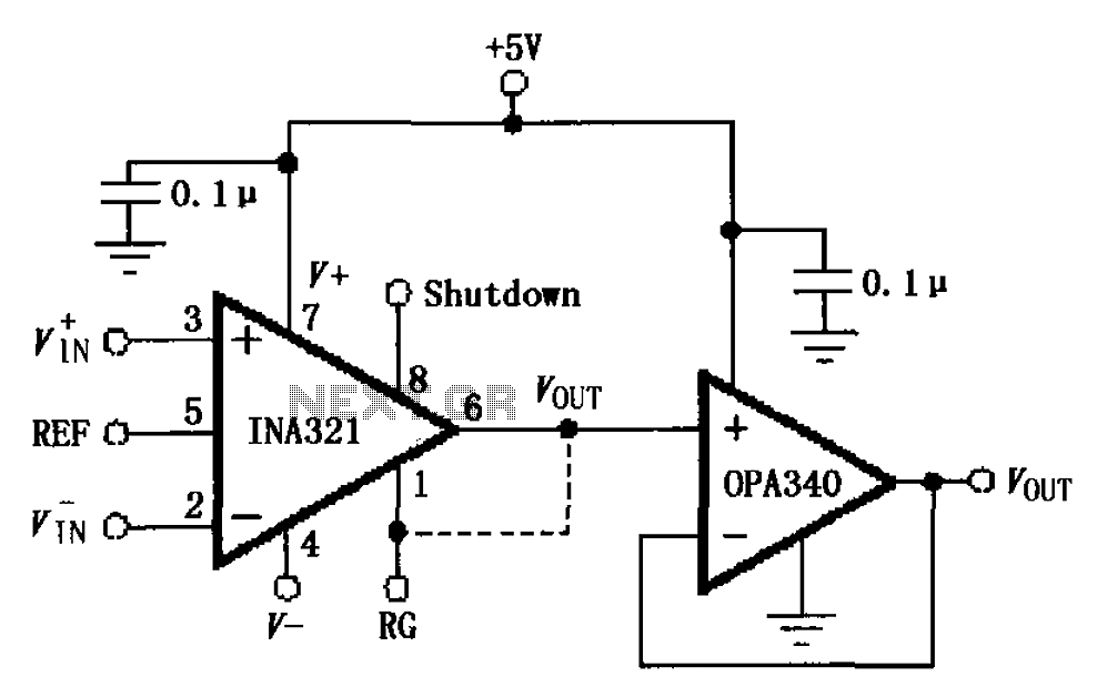
The circuit depicted in the figure consists of an OPA340 operational amplifier configured as a voltage follower, serving as an output buffer for the INA321/322 output. The optimal load impedance for the INA321/322 is 10k ohms or greater. A...
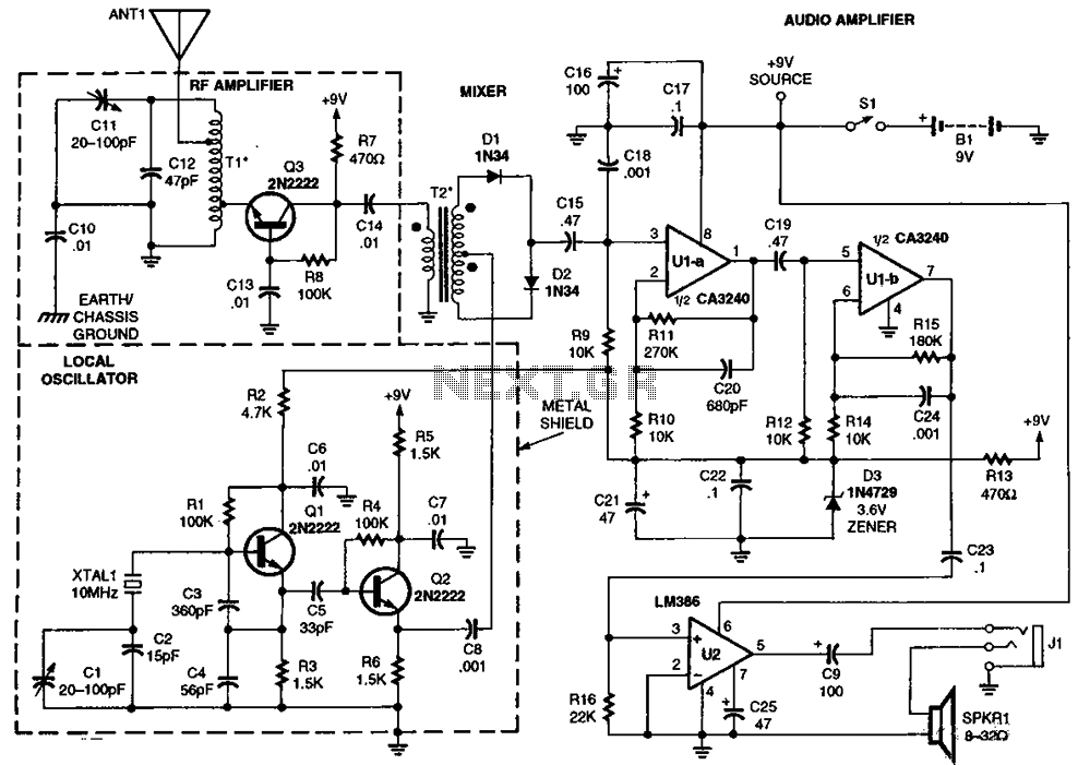
The RF amplifier Q3 connects to diodes D1 to D4 within the mixer. Transistors Q1 and Q2, through transformers T1 and T2, facilitate the injection of liquid oxygen at 10 MHz for diodes D1, operational amplifier U1A, and U1B....
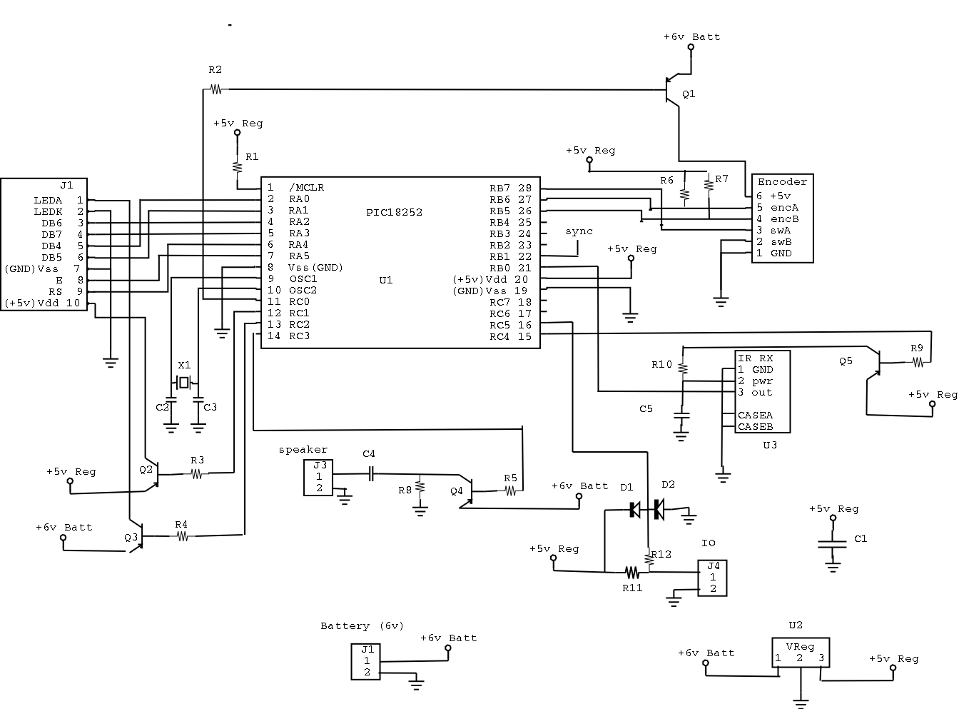
The most significant omission was that the DRUID did not accept confirmation codes (i.e., the solution to the clue) and did not provide directions to the next clue site. Instead, teams had to call in and confirm with Game...
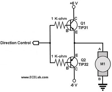
The following circuit illustrates a two-transistor DC motor driver circuit diagram. This circuit utilizes the TIP32 transistor. Features: operates in... The two-transistor DC motor driver circuit is designed to control the operation of a DC motor using two NPN transistors,...