
LED Traffic Lights for Games

The described circuit utilizes a 555 timer configured in astable mode to generate a pulse-width modulation signal that drives a 4017 decade counter IC. The 4017 is designed to sequentially activate its output pins, in this case controlling three LEDs that simulate a traffic light system. The output sequence typically follows the pattern of red, yellow, and green lights, mimicking standard traffic signal behavior.
The circuit begins with the 555 timer, which is set up with appropriate resistors and capacitors to determine the frequency and duty cycle of the output signal. The output from the 555 timer is connected to the clock input of the 4017 IC. As the timer generates pulses, the 4017 counts these pulses and sequentially activates its output pins (Q0, Q1, Q2) connected to the LEDs.
Each LED is connected through a current-limiting resistor to prevent excessive current flow, ensuring the longevity of the LEDs. The diodes used in the circuit are 1N4148, which are suitable for signal-level applications and help protect the circuit from reverse voltage conditions.
Powering the circuit can be achieved using either a 9V battery or a 12V battery/power supply, providing flexibility in terms of power sources. The design effectively demonstrates basic principles of digital electronics and timing circuits while serving a practical purpose in simulating traffic light operation.This schematic uses the 555 timer and the 4017 IC to drive 3 LED, to simulate the trafic lights. All diodes are iN4148. The circuit is operated with 9 volt battery or with a simple 12V battery or power supply. 🔗 External reference
Related Circuits
The automobile interior lights fader circuit diagram is designed to gradually brighten and dim the interior lights of older vehicles. This circuit utilizes the LM324 low-power operational amplifier as its core component. The automobile interior lights fader circuit is an...
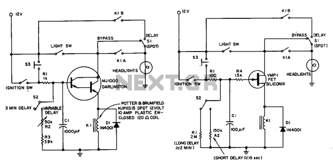
This circuit maintains the headlights of an automobile in an on state temporarily. It also ensures that the lights turn off automatically, even if the user forgets to switch them off manually. The shut-off delay is activated only when...
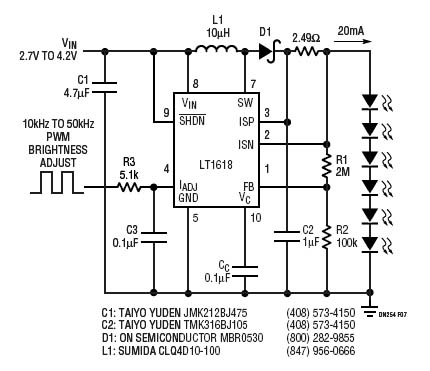
The LT1618 not only offers an accurate input current limit but can also be utilized to deliver a regulated output current suitable for current-source applications. The LT1618 is a precision current limiting device that can be effectively employed in various...
This relay circuit is controlled by nearly any type of infrared remote controller. The circuit operates under the assumption that most remote controllers utilize high-frequency signals. The relay circuit described functions by receiving signals from an infrared (IR) remote control,...

Function generators are essential in the design, testing, and operation of encoders, modulators, demodulators, and measurement instruments. This document presents an economical method to construct a bus-controlled sinewave oscillator that exhibits exceptionally low distortion. The circuit produces a sinusoidal...
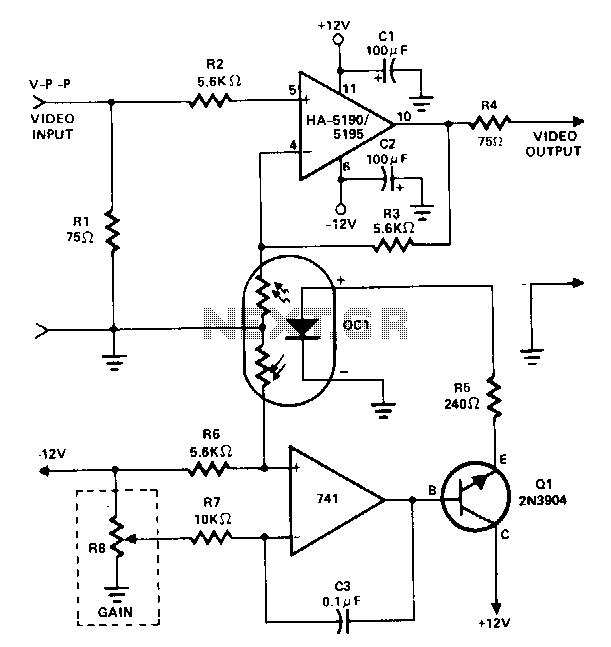
This amplifier utilizes a cascaded operational amplifier (op amp) integrator and a transistor buffer, Q1, to drive the gain control element. With a minor modification, the HA-5190/5195 stage is configured as a conventional non-inverting op amp and includes input...