
LED VoltMeter Circuit

The LED voltmeter circuit comprises a series of components designed to accurately reflect the state of the battery charge. The primary components include four Zener diodes, each selected to correspond to specific voltage levels indicative of the battery's charge status. These Zener diodes are connected in parallel with the LEDs, ensuring that each LED illuminates when the voltage across the diode exceeds its breakdown voltage.
The Zener diodes are chosen based on the desired voltage thresholds: for instance, a 13.6V Zener diode will activate the first LED when the battery voltage is at or above this level. The subsequent Zener diodes could be rated at 14.0V, 14.4V, and 14.8V to correspond with increasing battery voltages, thus illuminating additional LEDs as the battery approaches a fully charged state.
The circuit may also incorporate a resistor in series with each LED to limit current and prevent damage. The resistors are calculated based on the forward voltage drop of the LEDs and the supply voltage to ensure proper operation.
In cases where the battery voltage falls below 10.6 volts, a cutoff mechanism can be included to prevent any LED from lighting up, indicating a critically low charge. This feature is essential for protecting battery health and preventing deep discharge.
The overall design is straightforward, allowing for easy assembly and integration into battery monitoring systems. The LED voltmeter serves as a visual indicator, providing immediate feedback on the battery's state of charge and facilitating timely maintenance or recharging actions as necessary.A Simple LED Voltmeter to Monitor the charge level in Lead Acid Battery or Tubular battery. The terminal voltage of the battery is indicated through a four level LED indicators. The nominal terminal voltage of a Lead Acid battery is 13. 8 volts and that of a Tubular battery is 14. 8 volts when fully charged. The LED voltmeter uses four Zener diodes to light the LEDs at the precise breakdown voltage of the Zener diodes. Usually the Zener diode requires 1. 6 volts in excess than its prescribed value to reach the breakdown threshold level. When the battery holds 13. 6 volts or more, all the Zener breakdown and all LEDs light up. When the battery is discharged below 10. 6 volts, all the LEDs remain dark. So depending on the terminal voltage of the battery, LEDs light up one by one or turns off. 🔗 External reference
Related Circuits
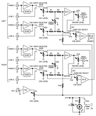
The mixer circuit features two line inputs and two microphone inputs, along with two line outputs. The microphone inputs are designed for low-impedance dynamic microphones with an impedance range of 200-1000 ohms. This simple mixer was specifically designed to...
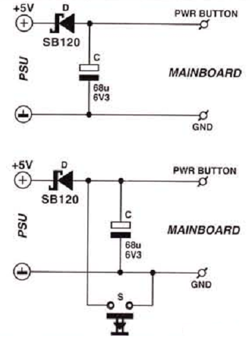
Many enthusiasts utilize their PCs as data loggers, controllers, or web servers. In such instances, it is crucial to ensure that the machine remains powered for as much time as possible, even during a power outage or if the...
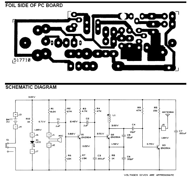
The frequency range for the FM transmission band is 90 MHz (megahertz, or 90 million cycles per second). Due to the variable tuned circuit in the FM transmitter, it can be tuned to a specific frequency within the local...
This is an aerial current power supply with a continuously adjustable stabilized output ranging from 0 to 30VDC. The circuit also incorporates an electronic current limiter that effectively controls the output current from a few milliamperes (2 mA) to...
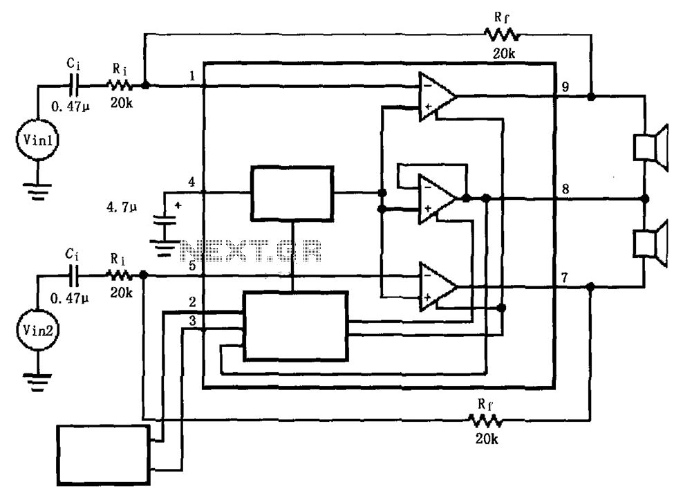
The LM4911 is presented in a configuration that does not utilize an output capacitor (OCL) for its power circuit. This design eliminates the need for squelch control (Mute), as the shutdown control (SD) responds more rapidly than the squelch...
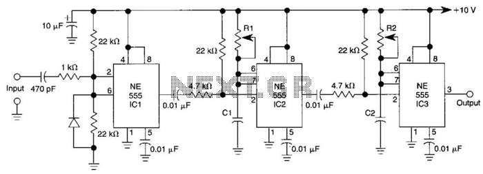
Three 555 IC timers are utilized in this circuit to create a simple delayed-pulse generator. IC1 functions as a waveform shaper to generate a rectangular waveform. IC2 generates a delaying pulse that triggers IC3 on the trailing edge of...