
Driving 72 leds with 555 timer

The proposed circuit utilizes a 555 timer in astable mode to drive 72 LEDs concurrently. The 555 timer is a versatile integrated circuit capable of generating precise timing sequences and is commonly used in various applications, including LED drivers.
To ensure the circuit operates safely and effectively, a few critical considerations must be addressed. First, the power supply voltage should be compatible with the 555 timer and the forward voltage ratings of the LEDs. Typically, a 5V to 15V supply is suitable for the 555 timer, while the LEDs may require a lower voltage, generally around 2V to 3V depending on their color and type.
The circuit can be designed as follows:
1. **555 Timer Configuration**: Connect the 555 timer in astable mode. This involves connecting pins 2 and 6 together, with a resistor (R1) connected from pin 7 to the supply voltage and another resistor (R2) from pin 7 to pin 6. A capacitor (C1) should be connected from pin 6 to ground. The values of R1, R2, and C1 will determine the frequency of the output signal, which should be set to a frequency that allows the LEDs to appear continuously lit rather than blinking.
2. **LED Connection**: Connect the anodes of the LEDs to the output pin (pin 3) of the 555 timer. Connect the cathodes of the LEDs to ground. To ensure that the LEDs operate safely, it is advisable to include current-limiting resistors in series with each LED. The resistor value can be calculated using Ohm’s Law: R = (V_supply - V_LED) / I_LED, where V_supply is the supply voltage, V_LED is the forward voltage of the LED, and I_LED is the desired current through the LED (typically around 20mA for standard LEDs).
3. **Power Considerations**: When driving a large number of LEDs, it is essential to ensure that the total current does not exceed the current rating of the 555 timer. If the total current exceeds the rating, consider using a transistor or MOSFET as a switch to drive the LEDs, allowing the timer to control the gate of the transistor, which in turn will handle the higher current for the LEDs.
4. **Heat Management**: With 72 LEDs, heat dissipation may become an issue. Ensure that the components, especially the 555 timer and any transistors used, are rated for the expected power dissipation. Heat sinks may be necessary for higher power applications.
5. **Testing and Validation**: Once the circuit is assembled, it is crucial to test the circuit with a multimeter to ensure proper voltage levels and current flow through the LEDs. Observe the operation for an extended period to confirm reliability and thermal performance.
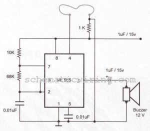
By addressing these considerations, the circuit can be optimized for safety and longevity while effectively driving the 72 LEDs.Make a circuit with a 555 timer to run 72 LEDs all at the same time. I have already made a circuit, but am not sure If it will work safe and long or not. I am putting the picture of the circuit and I want anybody who can help to look at it and see if it needs some extra components. Please add them on the circuit or explain instructions to add. 🔗 External reference
Related Circuits
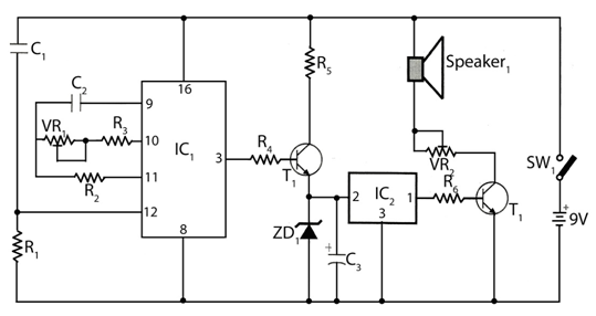
The circuit timer with a musical alarm utilizes a well-known CMOS oscillator/divider integrated circuit (IC1). Although this circuit operates at 9V, its standby current drain is minimal. The time delay of the timer circuit can be adjusted by modifying...
Q1 and Q2 create an ALL-ON ALL-OFF circuit that, when in the off state, draws negligible current. P1 initiates the circuit, activating the relay and powering the two integrated circuits (ICs). The lamp is energized through the relay switch,...
How to create a hydrogen generator using a 555 timer circuit with Pulse Width Modulation (PWM). This PWM circuit can generate hydrogen on demand. The hydrogen generator circuit utilizing a 555 timer operates by controlling the duty cycle of the...
The basic circuit illuminates up to ten LEDs in sequence, following the rhythm of music or speech picked up by a small microphone. The expanded version can drive up to ten strips, formed by up to five LEDs each,...
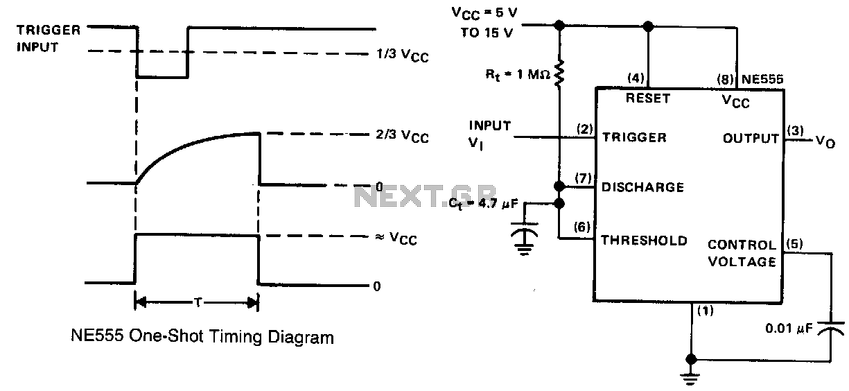
This simple circuit consists of only two timing components, Rr and Cr, the NE555 timer, and a bypass capacitor C2. Although C2 is not essential for operation, it is recommended for noise immunity. During standby, the trigger input terminal...
The circuit of a burglar alarm utilizing IC timer 555/556 functions as a security measure to prevent unauthorized entry into a premises. The alarm generates a loud sound when a thin wire connecting resistor R1 with pin 4 of...