
LED VU Meter with LM3914N

The input signal is taken to a variable attenuator which enables the sensitivity of the circuit to be set at the correct level. The signal is then passed to a low gain common emitter amplifier based on Q1 which gives a tenfold boost in the sensitivity of the circuit. C2 couples the output from Q1 to the input of IC1.
R5 is the input bias resistor for IC1, and D7 protects IC1 against an excess negative input voltage. R6 sets the current to each LED at about 12mA, but as IC1 responds only to positive half cycles the LEDs can switch on for a maximum of 50% of time. This gives an effective LED current a 6mA. The quiescent current consumption of the unit is about 8mA rising to an absolute maximum or 44mA with all six LEDs activated.
To calibrate the unit, a 0dB test signal should be fed into the equipment and R1 adjusted for the lowest sensitivity that does not cause the 0dB LED to extinguish. The input impedance of the unit is about 80k and it will only lightly load the monitored equipment.
The LM3914N is a versatile integrated circuit designed for driving LED displays, particularly in applications such as audio level meters. In this circuit, the LM3914N is configured to operate in bar mode, where multiple LEDs illuminate in response to increasing input voltage levels. The circuit is designed to activate specific LEDs based on predetermined dB levels, allowing for a visual representation of audio signal strength.
The input stage of the circuit employs a variable attenuator, which allows the user to adjust the input signal level to match the sensitivity required for accurate meter readings. Following the attenuator, a low-gain common emitter amplifier (Q1) amplifies the signal, providing a tenfold increase in sensitivity. This amplification is crucial for ensuring that even low-level audio signals can be accurately represented on the LED display.
Capacitor C2 serves to couple the amplified output from the transistor to the input of the LM3914N, ensuring that only the desired frequency components are passed through. Resistor R5 provides the necessary biasing for the LM3914N, while diode D7 acts as a protective element, safeguarding the IC from potentially damaging negative voltage spikes.
Resistor R6 plays a critical role in determining the current flowing through each LED. By setting the current to approximately 12mA, the circuit allows for bright and visible LED indicators. However, since the LM3914N only responds to the positive half of the input signal, the effective current through the LEDs is approximately halved to 6mA, resulting in efficient power consumption while maintaining visibility.
The quiescent current consumption of the circuit is relatively low at around 8mA, making it suitable for battery-operated devices. However, when all six LEDs are illuminated, the current draw can increase to a maximum of 44mA, which should be considered in power supply design.
Calibration of the VU meter is performed by feeding a 0dB reference signal into the input and adjusting resistor R1 until the 0dB LED indicator remains lit without extinguishing. This step ensures that the meter is accurately calibrated for the specific audio equipment being monitored.
Overall, this circuit design effectively combines audio signal processing with visual display technology, providing a reliable and user-friendly VU meter suitable for various audio applications.The circuit is based on an LM3914N bar graph display driver device (IC1), which can be used to drive up to ten LEDs. This is connected so that with OV12 at the input only the first LED indicator switches on. This simple peak reading VU meter circuit uses six LEDs to indicate six signal levels at 14, 8, 3, 0, +3, and +6dB, or any other levels having the same spacing (e.g.
17, 11, 6, 3, 0, and +3dB, if preferred). About 24mV peak to peak is needed in order to activate the highest LED indicator, so the circuit is sufficiently sensitive to be used with any normal item of audio equipment. With the input raised to OV24 the second LED switches on as well; OV36 causes three LEDs to switch on and so on up to an input of 1V2 or more whereupon all ten LEDs are activated. In this circuit only LEDs 1, 2, 3, 5, 7 and 10 are included in the display, and these are D1 to D6 respectively.
The input signal is taken to a variable attenuator which enables the sensitivity of the circuit to be set at the correct level. The signal is then passed to a low gain common emitter amplifier based on Q1 which gives a tenfold boost in the sensitivity of the circuit.
C2 couples the output from Q1 to the input of IC1. R5 is the input bias resistor for IC1, and D7 protects IC1 against an excess negative input voltage. R6 sets the current to each LED at about 12mA, but as IC1 responds only to positive half cycles the LEDs can switch on for a maximum of 50% of time. This gives an effective LED current a 6mA. The quiescent current consumption of the unit is about 8mA rising to an absolute maximum or 44mA with all six LEDs activated.
To calibrate the unit, a 0dB test signal should be fed into the equipment and R1 adjusted for the lowest sensitivity that does not cause the 0dB LED to extinguish. The input impedance of the unit is about 80k and it will only lightly load the monitored equipment. 🔗 External reference
Related Circuits
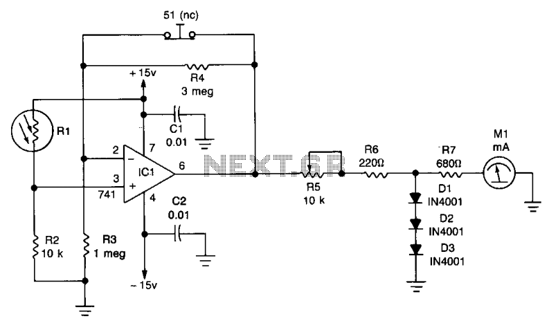
One leg of the photocell (R1) is connected to the +15 volt supply, while the other end is linked to ground through resistor R2, creating a voltage-divider network. The non-inverting input of the 741 operational amplifier (IC1) is connected...
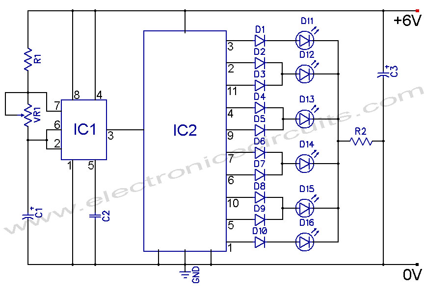
4017 LED Knight Rider Running Light Circuit Diagram. In this 4017 Knight Rider circuit, the 555 timer is configured as an oscillator. It can be adjusted to produce a variety of timing intervals. The 4017 LED Knight Rider circuit utilizes...
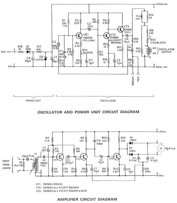
The AVO VCM 163 is a tube tester capable of measuring tube electrode currents, such as plate and screen currents, as well as mutual conductance simultaneously. It is the most advanced tube tester developed by AVO. The voltages applied...
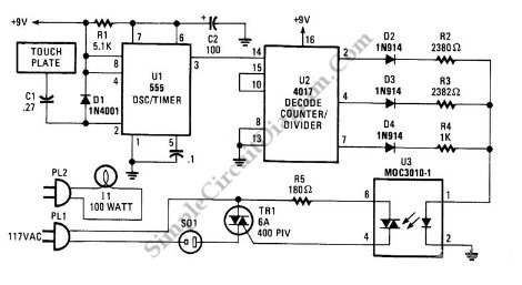
This is a three-mode lamp dimmer circuit with touch control. This circuit can be used to control a lamp in three operation modes: dim, off, and bright. It utilizes a NE555 timer. The three-mode lamp dimmer circuit designed with touch...
Most analog multimeters are capable of measuring resistance over a wide range of values, but they can be inconvenient to use due to the reverse reading scale, which is also non-linear. Analog multimeters, often referred to as VOMs (Volt-Ohm-Milliammeter), are...

This is a simple circuit where an LED turns on only after a predetermined time once the power supply is activated. Initially, when the power supply is turned on, the transistor remains off. The capacitor charges through the preset...