
Lie Detector

The lie detector circuit operates on the principle that skin resistance varies with emotional states, particularly during stress or deception. The primary component of this circuit is a microcontroller or an operational amplifier configured to measure the resistance of the skin. The circuit typically includes electrodes that are attached to the skin, which capture the galvanic skin response (GSR).
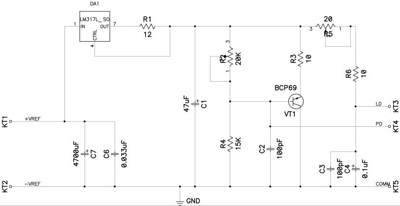
The schematic may include a resistor divider circuit, where the skin resistance is one of the resistors, and a fixed resistor is used to create a voltage drop that can be measured. The output from this voltage divider can be fed into an analog-to-digital converter (ADC) within the microcontroller, which processes the signal and determines the skin resistance value.
To provide a visual indication of the measured resistance, the circuit may incorporate an LED display or an LCD screen. The microcontroller can be programmed to trigger the visual indicators based on predefined thresholds of skin resistance, which correlate to the likelihood of deception.
Power supply considerations are also essential; the circuit may be powered by a battery or a DC power source, with appropriate voltage regulation to ensure stable operation of the electronic components. Additional features could include audio alerts or logging capabilities to record the resistance values over time for further analysis.
Overall, the circuit design combines various electronic components to create a functional lie detector that visually indicates changes in skin resistance, thereby providing insights into the emotional state of the subject being tested.The lie detector presented here has been designed to detect skin resistance and to give visual indication, verified electronic project. 🔗 External reference
Related Circuits

The detector is designed to sense and signal to another circuit when an appliance is connected to the mains voltage. An optocoupler, identified as IC1 in the circuit, is utilized for this purpose. The light-emitting diode within the optocoupler...

When the tank is cleaned the fish are removed and placed in a small amount of the tank water. The problem is that fish don’t like rapid temperature fluctuations. A simple in-tank or stick-on thermometer would have sufficed, but...

Dynamic flip-flops ignore pulses at their inputs that are shorter than 40 ns or do not have TTL levels. This means that TTL flip-flops are not well-suited for capturing noise pulses with unknown durations and magnitudes. This issue is...
This includes immunity to power line transients as well as those that may occur during power-on and power-off cycling. The parameters of many electronic components like ICs are rarely specified during periods of changing input power. Special laser diode...
This circuit is designed to indicate when room noise exceeds a predetermined threshold, utilizing a flashing LED to signal this condition. Three fixed noise levels are selectable: 50 dB, 70 dB, and 85 dB. The circuit employs two operational...
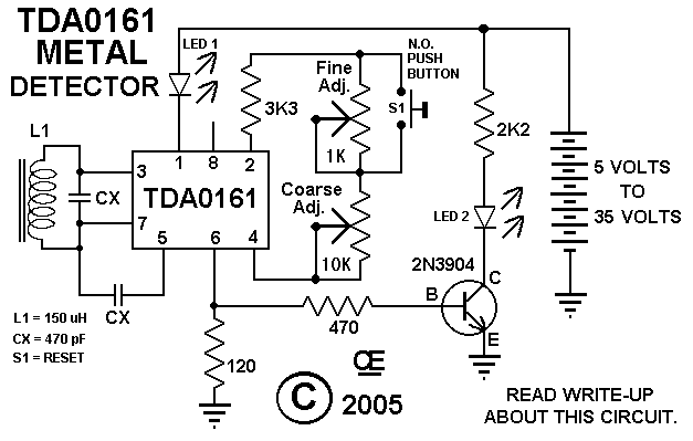
This circuit features an LED indicator with two identical LEDs depicted in the schematic. The modification in Advanced Schematic-2 enhances the detector's sensitivity by incorporating a manual reset function to eliminate the built-in hysteresis of the integrated circuit (IC)....