
mains voltage detector

The circuit operates by utilizing an optocoupler to provide electrical isolation between the mains voltage and the control circuit. The design incorporates a bridge rectifier (B1) that converts the AC mains voltage to a DC voltage, allowing the LED in the optocoupler to function effectively. The potential divider formed by resistors R1 and R2, along with capacitor C1, ensures that the correct voltage and current levels are maintained for the LED to operate within its specified parameters.
When the appliance is switched on, the mains voltage is applied to the potential divider, allowing current to flow through the LED. The resulting illumination activates the photo-transistor within the optocoupler, enabling it to conduct and signal the downstream circuit. This feature is critical for applications requiring automatic detection and response to the appliance's operational status.
The circuit's design also emphasizes safety and reliability. The inclusion of fuse F1 serves as a protective measure, ensuring that the monitored appliance remains safeguarded from potential overloads or faults. The optocoupler's maximum switching voltage rating of 30 V further enhances the circuit's robustness, allowing it to handle varying operational conditions without failure.
In summary, this detector circuit is a versatile solution for monitoring appliance connectivity to mains voltage, with applications ranging from audio equipment integration to safety systems. Its efficient design and component selection make it suitable for a variety of electronic projects where reliable detection and signaling are required.The detector is intended to sense and signal to another circuit that an appliance is connected to the mains voltage. For this purpose, an optocoupler, IC1 in the circuit, is used. The light-emitting diode in this device is connected across the mains voltage rectified by bridge B1.
The mains voltage is applied to this bridge via potential divider R 1-C1-R2. When the capacitor has a value as specified in the diagram, the current through the diode is about 700 µA (for a mains voltage of 230 V). This results in sufficient light to make the photo-transistor conduct. The drop across the LED is about 1V. The detector draws a current only when the monitored equipment is switched on. It is intended to be built into the appliance whose mains connection is to be monitored and must, of course, be connected behind the mains on/off switch.
A possible application of the detector is in the preamplifier described in this blog (DIY: From vinyl to compact disc`). When it senses that the record player is being switched on, it can be used to link the Line-In input of the soundcard automatically to the preamplifier.
Another possible application is its use as a power-on reset circuit in a protection system. Transistor T1 can switch currents of up to 10mA; in the prototype, the knee voltage of the transistor was around 200mV at a current of 20mA. The maximum permissible switching voltage of the optocoupler is 30 V. Fuse F1 is added to allow a fuse to be omitted on the monitored appliance. 🔗 External reference
Related Circuits

An LT1172 generates positive and negative voltages from a 5-V input. The LT1172 is configured as a step-up converter. To generate the negative output, a charge pump is used. C2 is charged by the inductor when D2 is forward-biased...

The schematic diagram is derived from the circuit for an Adjustable High Voltage Power Supply, which can output voltages ranging from 0 to 1000V. A suitable source of alternating voltage for the high voltage converter is 12V / 800mA....
A simple voltage probe circuit is depicted in the schematic diagram below. This circuit is highly useful for testing or troubleshooting discrete or integrated circuits. The simple voltage probe circuit serves as an essential tool for engineers and technicians engaged...
This circuit was designed to detect when a call is incoming in a cellular phone (even when the calling tone of the device is switched-off) by means of a flashing LED. The device must be placed a few centimeters...

The LM317 is capable of providing extremely good load regulation, but a few precautions are needed to obtain maximum performance. For best performance, the programming resistor (R1) should be connected as close to the regulator as possible to minimize...
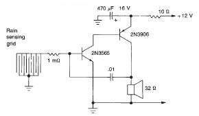
This rain detector electronic circuit project is a simple alarm circuit that activates an audio warning when liquid is detected on the sense pad. The circuit diagram is based on two transistors. When the sense pad conducts, transistors Tr1...