
Light Activated SwitchCircuit Based On The LM311 IC

The Light Activated Switch Circuit utilizes the LM311 voltage comparator to control the switching of a load based on ambient light levels. The circuit typically consists of a photodiode or phototransistor that detects light intensity. When the light level exceeds a predetermined threshold, the output of the LM311 changes state, activating a relay or transistor that controls the load.
In this configuration, the photodiode is connected to the inverting input of the LM311, while a reference voltage is applied to the non-inverting input. The reference voltage can be adjusted using a potentiometer, allowing for fine-tuning of the light sensitivity. When the light intensity surpasses the reference voltage, the LM311 output transitions from low to high, which can be used to drive a relay or transistor, thereby switching on the connected load.
The circuit may also include additional components such as resistors for current limiting and capacitors for noise filtering. Proper layout and component selection are crucial for ensuring the circuit's responsiveness to light changes and minimizing false triggering from ambient light fluctuations. This type of circuit is commonly employed in applications such as automatic street lighting, garden lights, and other systems that require light-sensitive control.The following circuit shows about Light Activated Switch Circuit Diagram. This circuit based on the LM311 IC Features: voltage comparator circuit .. 🔗 External reference
Related Circuits
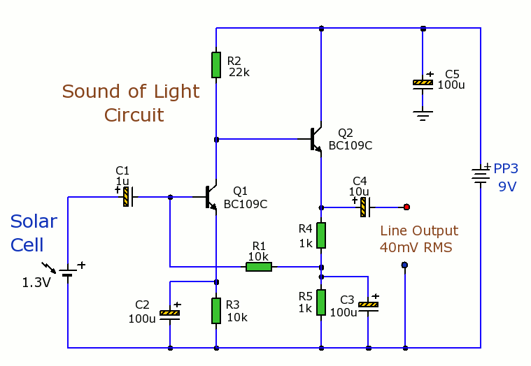
Solar Cells Light-Sound Converter. This is an experimental circuit that converts light into sound. The Solar Cells Light-Sound Converter is an innovative circuit designed to transduce light energy into acoustic signals. This experimental setup utilizes photovoltaic cells to capture ambient...

With the storm season recently upon us, it is common to switch car headlights on during the daytime. Unfortunately, it is easy to forget to turn them off again when parking, resulting in a flat battery. This circuit will...
This sound-controlled lighting circuit design is utilized to adjust the brightness of connected lights in synchronization with captured sound. The sound-controlled lighting circuit operates by detecting audio signals through a microphone or sound sensor. The circuit typically consists of several...

This article outlines a lighting circuit designed to create a glowing firebox effect while providing constant illumination for classification lamps and an interior cab light. It includes comprehensive information necessary for constructing the circuit, such as a detailed schematic,...
This handy little circuit can tell the difference between darkness and light, making it very useful for switching on and off signs, porch lights or other things when it gets dark or light. More: R1 Adjusts sensitivity The circuit described...
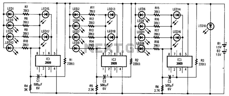
Three individual flashing circuits utilizing an LM3909 LED flasher/oscillator IC create the illusion of a pseudo-random firing order. The capacitors CX1, CX2, and CX3 control the blink rate, which ranges from 0.3 to 0.8 seconds. The wide tolerance range...