
Light/Dark Detector relay

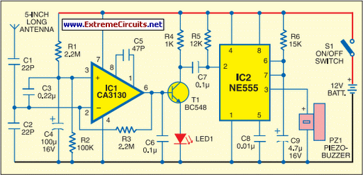
The circuit described is a light-sensitive switch, commonly known as a light-dependent resistor (LDR) circuit. This type of circuit utilizes an LDR, which is a resistor that changes its resistance based on the intensity of light falling on it. In the absence of light, the resistance of the LDR increases, allowing the circuit to detect darkness.
The primary components of this circuit include the LDR, a transistor (which acts as a switch), a resistor (R1, which adjusts the sensitivity of the circuit), and an output load such as a relay or a light bulb. The configuration typically involves the LDR connected in a voltage divider arrangement with R1. The output from this divider is fed into the base of the transistor.
When the ambient light level falls below a certain threshold (determined by the values of R1 and the LDR), the voltage at the base of the transistor reaches a level sufficient to turn it on. This allows current to flow from the collector to the emitter, thereby energizing the output load. Conversely, when the light level increases, the resistance of the LDR decreases, causing the voltage at the base of the transistor to drop, turning the transistor off and deactivating the load.
The sensitivity of the circuit can be finely tuned by adjusting the value of R1. A higher resistance value will increase the sensitivity, allowing the circuit to react to lower light levels, while a lower resistance will require brighter light to turn the circuit off. This feature makes the circuit versatile for various applications, including outdoor lighting systems and automatic signage.
In summary, this light-sensitive circuit effectively detects changes in light levels and can be utilized to control various devices based on ambient light conditions, enhancing energy efficiency and automation in lighting solutions.This handy little circuit can tell the difference between darkness and light, making it very useful for switching on and off signs, porch lights or other things when it gets dark or light. R1 Adjusts sensitivity 🔗 External reference
Related Circuits
The metal detector circuit comprises several key components, including a power circuit, a sine wave oscillator, a PLL (phase-locked loop) circuit, and a hybrid amplifying circuit. The power circuit is made up of batteries GBI and GB2, filter capacitors...
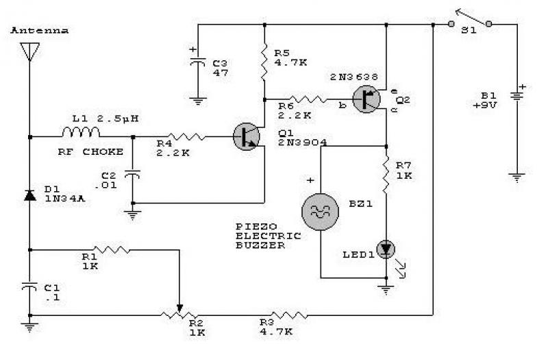
This circuit responds to RF signals below the standard broadcast band up to over 500 MHz and provides both visual and audible indications when an RF signal is detected. By adjusting the bias of diode D2 with the R2...
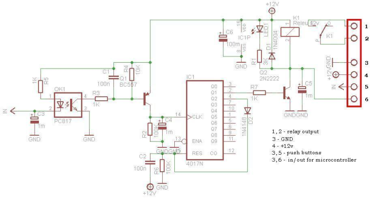
This circuit is operating the room illuminates. The basic component of the circuit is a IC1 (CD4017). Push buttons room are connected by normally wired to the circuit. All circuit is separately by optocoupler, which means that the circuit...
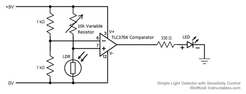
The schematic diagram for the circuit is provided in the accompanying image. As indicated by its name, a comparator is designed to compare two specified voltages. The circuit includes a pair of 1K resistors. A comparator circuit typically utilizes operational...
When activated by pressing a button, this time delay relay will activate a load after a specified amount of time. This time is adjustable to whatever you want simply by changing the value of a resistor and/or capacitor. The...
This portable mobile transmission detector can detect the presence of an activated mobile phone from a distance of 1.5 meters. It is designed to prevent the use of mobile phones in examination halls, confidential areas, and other restricted environments....