
ir infrared detector circuit diagram

An infrared (IR) detector circuit can be designed to test the functionality of remote control units by detecting the IR signals they emit. The basic components of such a circuit include a photodiode or phototransistor, which serves as the IR light sensor, and an LED or a buzzer to indicate the presence of the IR signal.
The circuit operates by positioning the photodiode in the line of sight of the remote control. When the remote control is activated, it emits an IR signal that the photodiode detects. The photodiode generates a small current in response to the incoming IR light. This current can be amplified using a transistor to drive an LED or buzzer, providing a visual or audible confirmation that the remote control is functioning properly.
To build the circuit, the following components are typically required:
1. Photodiode or phototransistor (e.g., BPW34 or similar)
2. NPN transistor (e.g., 2N3904 or similar) for signal amplification
3. Resistors (for biasing the transistor and limiting current to the LED)
4. An LED or a buzzer for output indication
5. A power supply (typically a 9V battery or a similar DC source)
The circuit can be assembled on a breadboard for prototyping before finalizing the design on a printed circuit board (PCB). Care should be taken to ensure proper orientation of the photodiode and other polarized components. Additionally, the circuit should be housed in a suitable enclosure to prevent damage and ensure ease of use.
By utilizing this IR detector circuit, users can quickly diagnose whether their remote control is operational, enabling them to troubleshoot issues effectively and maintain their control over television viewing.Men in particular enjoy the convenience of television remote controls often to the annoyance of their female partners. Men apparently want to know what they re missing when the TV is tuned to a particular program, so they like to keep zapping to other channels.
With the remote control in their hands, they feel like they are the lord and master of the TV set. They are thus completely at a loss if the remote control doesn t work properly. There are many reasons why a remote control unit can malfunction, such as defective IR receiver in the TV set, a defect in the remote control, or empty batteries. Here a tester that can determine whether the remote control unit still emits an IR signal can come in handy.
If you want to keep the IR reins ?rmly in hand, you can build your own IR detector.. 🔗 External reference
Related Circuits
Amplifier with IC number TDA7293 for processing sound systems. This amplifier includes inputs for a radio, TV, stereo, or other line-level devices. It also features a phono input for a record player, guitar, microphone, or other unamplified sources. With...
The schematic for this project is significantly more complex than previous designs. There are four primary features in the design: (1) the ability to program the PIC microcontroller on the developed board, (2) control of a servo motor, (3)...
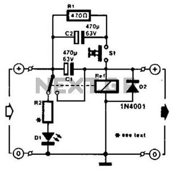
A method of adding overload protection to a power supply using a relay is shown. In each circuit, the relay must be reset by a momentary switch using a charge on capacitor C2. This prevents overload if the short...
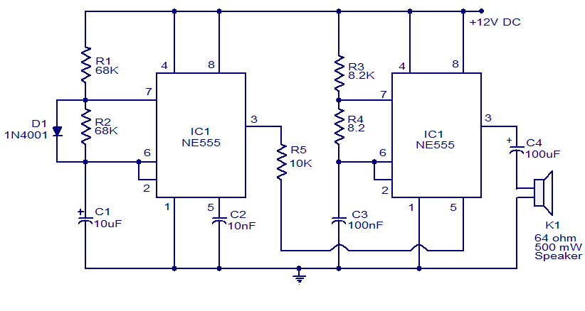
A variety of electronic circuits utilize the NE555 timer integrated circuit (IC). The circuit diagram presented illustrates a police siren based on two NE555 timer ICs, both configured as astable multivibrators. The circuit operates on a DC voltage supply...
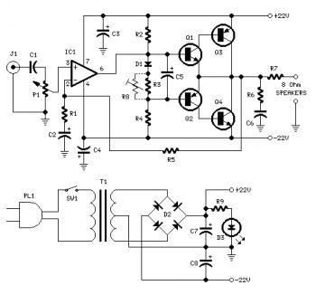
Proper grounding is essential for eliminating hum and ground loops. Connect the ground terminals of J1, P1, C2, C3, and C4 to the same point. Connect C6 to the output ground. An audio amplifier is an electronic device that...
The circuit operates by using a clock signal to drive four D-flip-flops in the control section, which store the on/off state of each current direction for the two stepper motor coils. The flip-flops create a finite state machine (FSM)...