
Soft Light Dimmer

The soft light dimmer circuit is designed to control the brightness of incandescent lamps or other resistive loads by adjusting the power delivered to the load. The core components of this circuit include the Insulated Gate Bipolar Transistor (IGBT) STGP10N50A, which is capable of handling high voltages and currents, making it suitable for dimming applications. The TS555 timer, configured in a suitable mode, generates a pulse-width modulation (PWM) signal that controls the gate of the IGBT.
In operation, the TS555 timer is configured in astable mode, producing a continuous square wave output. The frequency and duty cycle of this output can be adjusted by varying the resistor and capacitor values connected to the timer. This PWM signal is fed to the gate of the IGBT, which modulates the power delivered to the load. By adjusting the duty cycle of the PWM signal, the average voltage applied to the load can be varied, resulting in a change in brightness.
The circuit may also include additional components such as diodes for flyback protection, capacitors for filtering, and resistors for biasing, which help stabilize the operation and improve performance. Proper heat sinking for the IGBT is essential to ensure reliable operation, as it can generate significant heat during operation.
This soft light dimmer circuit is ideal for applications where gradual dimming is desired, such as in home lighting systems, stage lighting, or decorative lighting, providing users with control over the ambiance of their environment.This is circuit of soft light dimmer. This circuit uses the IGBT STGP10N50A and the TS555 timer as main components. Here is the circuit: The timer is. 🔗 External reference
Related Circuits
An automatic garage door opener, a seeded back lawn, a fireplace, and a refrigerator were offered. A flagpole was also requested, resulting in the installation of a 25-foot commercial flagpole. The owner has illuminated the flag at night to...
This light sensor switch circuit enables the automatic activation of a lamp when ambient light levels are low, such as during nighttime. The circuit keeps the lamp illuminated for a predetermined duration. When transistors T4 and T5 are activated,...
The lamps are usually used as ballast or electronic ballast inverter. Here it is used to reduce voltage capacitor reactance. Interesting is also the method of ignition of the auxiliary electrodes involved over 150 Ohm resistors. To start simply...
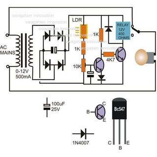
This circuit diagram illustrates a light-activated switch utilizing the National Semiconductor comparator IC LM311 and a light-dependent resistor (LDR). The configuration is based on a voltage comparator circuit centered around IC1. The non-inverting input of IC1 receives a reference...
This is an 8-bit up/down counter that, together with the "8-bit binary to 256 decimal (1 of 256) decoder," forms a run light. The circuit utilizes an 8-bit up/down counter, which is capable of counting both upwards and downwards...
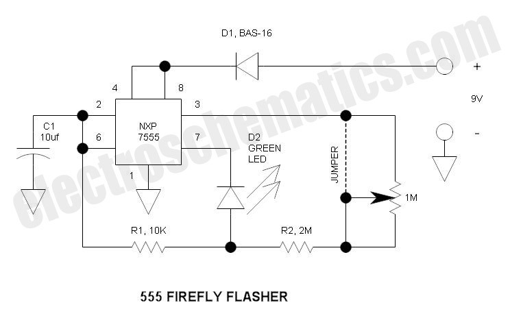
This circuit operates similarly to a standard 555 astable timer, with the distinction that the LED is integrated into the capacitor reset path. Consequently, when pin 7 discharges capacitor C1 to ground, a relatively high current flows through the...