
KNIGHT RIDER lights

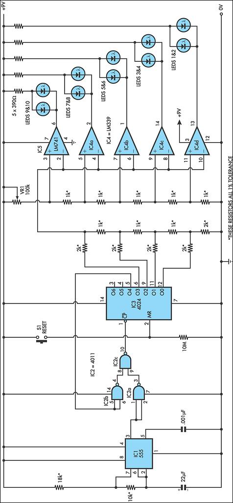
The circuit design features a square wave oscillator configured using a pair of NPN transistors arranged in a bistable multivibrator configuration. This arrangement generates a square wave output with a frequency determined by the values of the timing components involved, typically resistors and capacitors. The inclusion of the signal diode and a 39kΩ resistor serves to enhance the rise and fall times of the output waveform. These components mitigate issues that arise from slower transitions, which can cause unreliable operation in the CD 4017 decade counter IC.
The CD 4017 is a popular decade counter IC that counts from 0 to 9 and features ten output pins corresponding to each count. The clock input of the 4017 is sensitive to the characteristics of the incoming signal; thus, ensuring a sharp transition is critical for accurate counting. The output from the multivibrator is connected directly to the CLOCK INPUT of the CD 4017. When the multivibrator outputs a pulse, it triggers the counting sequence within the 4017.
In summary, this circuit effectively combines a multivibrator oscillator with a decade counter to create a reliable counting mechanism. The design ensures that the output waveform is optimized for the operational requirements of the CD 4017, thereby preventing potential counting errors or missed pulses that could result from slower signal transitions.The circuit consists of two building blocks. The first is a square wave oscillator made up of two transistors in a multivibrator arrangement and the second is a CD 4017 decade counter IC. The multivibrator contains two extra components to speed up the waveform and make it acceptable for all brands of 4017`s.
Unless the output has a very fast rise and fall characteristic, some 4017`s fail to operate properly. They either do not work at all or jump two or three outputs, losing the scanning effect. The two speed-up components are the signal diode and 39k resistor and are essential for reliable operation. The output of the multivibrator feeds into the CLOCK INPUT of the chip. From there is goes to a complex counting circuit inside the 4017. The circ 🔗 External reference
Related Circuits
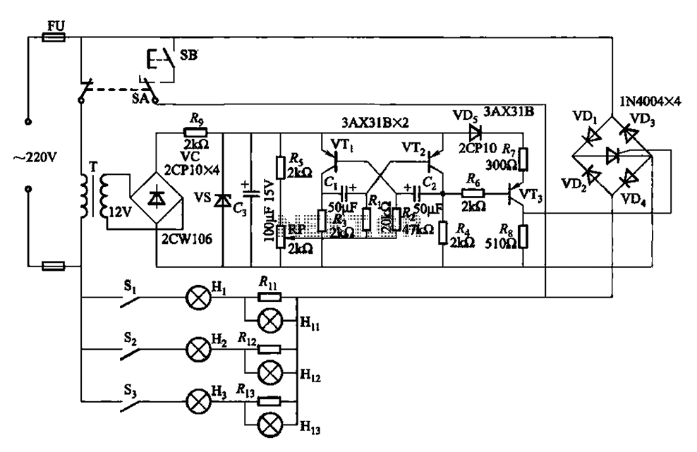
The self-excited multivibrator circuit utilizes transistors VTi and VT2 to generate an output signal that triggers a thyristor (VT3). An adjustment potentiometer (RP) is incorporated to modify the oscillation frequency, which in turn adjusts the flashing cycles of lights...
This circuit replicates the starting light sequence currently utilized by FISA for Formula One racing. It can be applied to slot car sets (such as HO scale AFX/Life Like/Tyco sets) or radio-controlled cars. IC1, a 555 timer integrated circuit,...
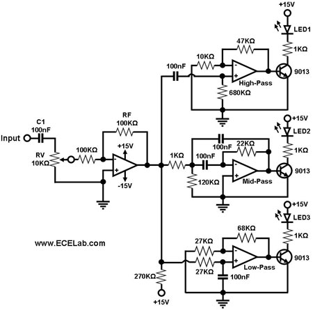
The simple circuit for converting an audio signal. The circuit basically consists of a buffer/amplifier stage and three filter circuits. The audio signal conversion circuit is designed to process audio signals efficiently while maintaining signal integrity. The circuit architecture includes...

Efficient automatic solar garden lights circuit with minimal components. The advantage is that it operates completely automatically, with the solar panel serving as a light detector. The efficient automatic solar garden lights circuit is designed to provide illumination using renewable...
This circuit operates at 73 MHz and is designed for controlling halogen lights through radio frequency remote control. The primary function is to toggle the power state of a halogen lamp. When the button on the remote control is...
This circuit must be connected to a 5 volt DC source. See my RR page for several 5 volt supplies. Note the flashing LED is optional, but looks so good on the top of a locomotive. The circuit described is...