
Water Level Controller

The water level controller circuit is designed to maintain the water level within a specified range in a tank, ensuring efficient operation and preventing overflow or dry running. The circuit typically employs a combination of sensors, control logic, and actuators to achieve this functionality.
The two modes of operation generally include the automatic filling mode and the automatic draining mode. In the automatic filling mode, the circuit activates a pump when the water level falls below a predetermined threshold, allowing the tank to refill. Conversely, in the automatic draining mode, the circuit can activate a drain valve when the water level exceeds a certain limit, enabling the tank to discharge excess water.
The circuit commonly utilizes float switches or capacitive sensors to detect the water level. These sensors provide feedback to a microcontroller or comparator circuit, which processes the input signals and controls the output devices accordingly. For instance, in a basic implementation, when the water level drops, the float switch closes, signaling the microcontroller to turn on the pump. Similarly, when the water level rises, another float switch may open, turning off the pump or activating the drain.
Additional components such as relays or MOSFETs may be incorporated to handle the higher currents required by pumps or valves. Protection features, such as fuses or circuit breakers, are also essential to prevent damage from electrical faults.
Overall, this water level controller circuit is critical in applications where maintaining a specific water level is necessary, such as in aquariums, industrial tanks, and agricultural irrigation systems. By automating the control of water levels, this circuit enhances operational efficiency and reduces the risk of water-related issues.Water level controller circuit described here control the water level inside a tank. There two modes available with this water level controller circuit. The. 🔗 External reference
Related Circuits

This circuit emits an intermittent beep or flashes an LED when the water level in a container reaches a predetermined point. It is designed to be mounted on top of the container, such as a plastic tank, using two...
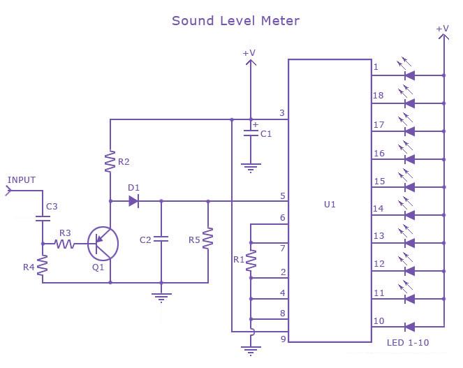
This is a single-chip sound level meter that can be used to display the sound level of an amplifier or simply the sound level from a microphone. The core component of the circuit is the IC LM3915 Audio Level...
The LM3915 is a VU meter LED bar graph driver that can control 10 LEDs. It operates in conjunction with a simple audio amplifier that drives a detector circuit, providing the necessary DC drive for the LM3915. The LM3915 IC...
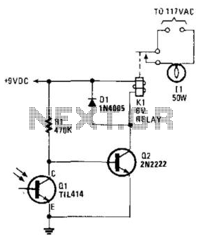
A phototransistor detects daylight. At dusk, it stops conducting, and Rl biases Q2, activating Kl, which turns on the light. At dawn, Ql begins to conduct, cutting off Q2. Kl deactivates, and the light turns off. The circuit utilizes a...
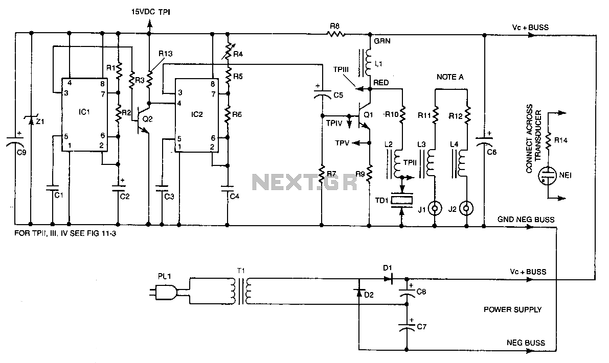
IC2 is a stable oscillator whose frequency and pulse width are determined by the values of R4, R5, R6, and C4. R4 is adjustable for precise frequency setting. The output from IC2 is at pin 3, which is capacitively...
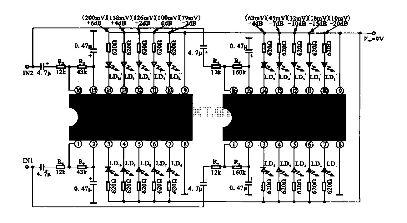
The circuit consists of dual drive integrated circuits (ICs) utilized in a 10 LED level meter configuration. The schematic features two TLM8101 driver ICs, which can be employed as alternatives. The 10 LED level meter circuit is designed to provide...