
Light Gate With Counter Using 555 And 4033

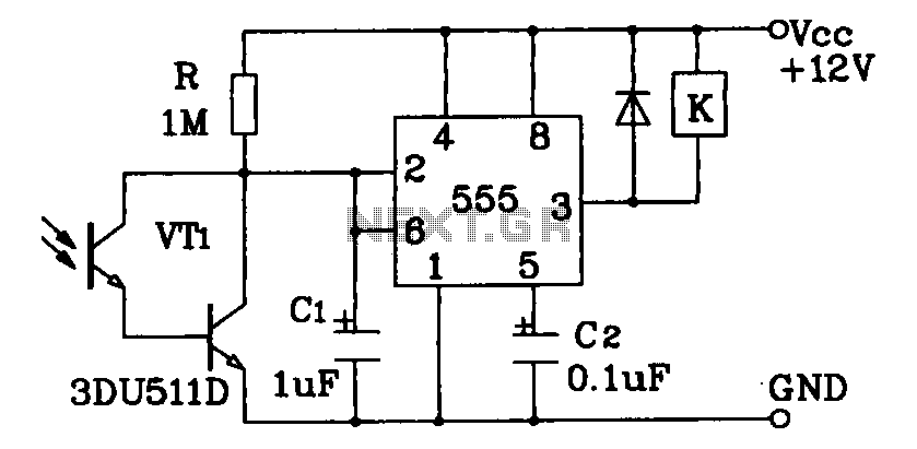
The circuit operates by utilizing a light gate to detect interruptions in an infrared beam, making it suitable for applications such as counting foot traffic or monitoring object passage. The IR diode (D1) emits infrared light that continuously illuminates the IR transistor (T1). In normal operation, T1 conducts based on the intensity of the light it receives from D1. The voltage at the collector of T1 is critical, as it must remain low enough to keep the next stage transistor (T2) off. The adjustment potentiometer (P1) allows for fine-tuning this voltage to ensure reliable operation under varying conditions.
When an object enters the detection zone and obstructs the light from D1 to T1, the conduction of T1 decreases, resulting in a higher collector voltage. This change produces a negative edge signal at the input of IC1, which is configured as a monostable multivibrator. The output from IC1 goes high for a set duration, which is determined by external components R3 and C1. During this time, a connected buzzer is activated, providing an audible indication of the interruption.
Once the buzzer has sounded, the negative edge produced triggers the clock input of IC2, a counter IC that counts each interruption. The internal binary-to-BCD decoder within IC2 simplifies the output management, allowing the counter state to be displayed on a 7-segment display through additional buffering components (IC3 and T3). The reset switch (S1) provides a means to clear the counter, enabling fresh counting sessions.
Careful construction of the circuit is necessary to ensure reliable performance. The positioning and shielding of T1 are particularly important, as it must be adequately illuminated while minimizing interference from ambient light. The use of a tube to house T1 can effectively reduce this interference, allowing for more accurate counting. The overall sensitivity of the circuit can be adjusted via P1, accommodating different environments and requirements. This circuit design exemplifies a practical application of infrared technology in counting and monitoring systems.The circuit described here counts the number of times that an infrared beam is interrupted. It could be used to count the number of people entering a room, for instance, or how often a ball or another object passes through an opening (handy for playing shuffleboard). The heart of the circuit consists of - you guessed it - a light gate! Diode D1 is an IR diode that normally illuminates IR transistor T1. The light falling on T1 causes it to conduct to a certain extent. The resulting voltage on the collector of T1 should be just low enough to prevent the following transistor (T2) from conducting. This voltage can be adjusted within certain limits using P1. As soon as an object comes between D1 and T1, the light shining on T1 will be partially or fully blocked, causing the IR transistor to conduct less current.
As a result, the voltage on its collector will increase, producing a brief rise in the voltage on the base of T2. This will cause T2 to conduct and generate a negative edge at IC1. This negative edge will trigger the monostable multivibrator, which will then hold the output signal on pin 3 high` for a certain length of time (in this case, one second).
At this point, two things will occur. First, a buzzer will be energized by the output of IC1 and produce a tone for approximately one second. When the buzzer stops, a negative edge will be applied to the clock input of IC2, causing the counter in IC2 to be incremented by 1.
IC2 is conveniently equipped with an internal binary-to-BCD decoder, so its outputs only have to be buffered by IC3 and T3 to allow the state of the counter to be shown on the 7-segment display. Switch S1 can be used to reset the counter to zero. If a one-second interval does not suit your wishes, you can modify the values of R3 or C1 to adjust the time.
Increasing the value of R3 lengthens the interval, and decreasing it naturally shortens the interval. The same is true of C1. When building the circuit, make sure that T1 is well illuminated by the light from D1, while at the same time ensuring that T1 sees` as little ambient light as possible.
This can best be done bytting T1 in a small tube that is precisely aimed toward D1. The longer the tube, the less ambient light will reach T1. The sensitivity of the circuit can be adjusted using P1. 🔗 External reference
Related Circuits
Darlington phototransistor type light-sensitive switch control circuit application. The Darlington type phototransistor serves as a sensitive element, capable of detecting low light levels for the detection of reflected light signals. The Darlington phototransistor circuit utilizes a pair of transistors configured...
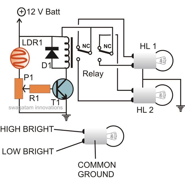
The circuit described here can be built and used in a vehicle for an automatic dipping and dimming operation of the headlamps in response to intense lights coming from opposite vehicle headlamps. This situation is often encountered while driving...
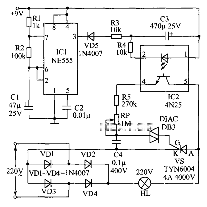
This circuit features an appealing Christmas lights setup. Upon activation, the lights (HL) gradually increase in brightness. Once they reach maximum brightness, they automatically dim, and upon reaching the lowest brightness, they gradually brighten again, creating a smooth transition...
NEC's UPB1008K is a Silicon RFIC specifically designed for handheld low-power, low-cost GPS receivers. The integrated circuit combines a low-noise amplifier (LNA) followed by a double-conversion RF/IF downconverter block and a phase-locked loop (PLL) frequency synthesizer on a single...
The Over-the-Top type of operational amplifier is ideal for use as a current sensor for battery charger applications. The design described here can be used with chargers for rechargeable batteries (Lead/acid or NiCd, etc.). The 5 V operating supply...
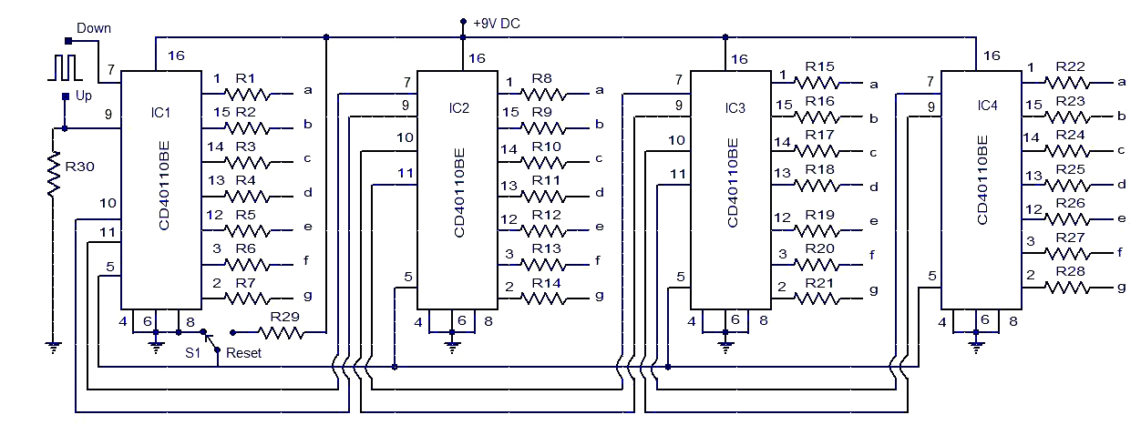
This circuit diagram illustrates a simple up/down counter suitable for various applications. It utilizes the CD40110BE IC, a CMOS decade up/down counter. Common cathode seven-segment displays are connected to the outputs of each IC. The display connected to IC1...