
200 LEDs Christmas Lights circuit
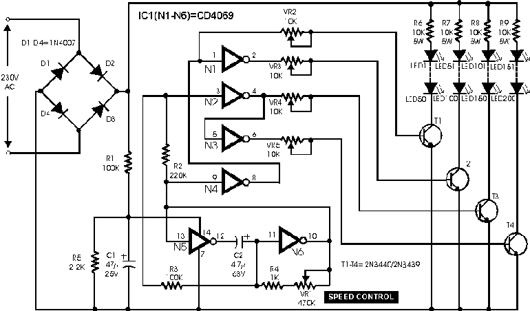
The circuit utilizes a CD4069UB CMOS hex inverter as the primary control element, which is a versatile component capable of performing various logic functions. The circuit is designed to operate directly from a 230V AC mains supply, which is first converted to a lower DC voltage suitable for the inverter IC. The bridge rectifier configuration (D1 to D4) ensures that the AC input is converted to a pulsating DC output. The filtering stage, composed of capacitor C1 and resistor R5, smooths the rectified output, yielding approximately 6V DC, which is then used to power the CD4069UB.
The inverter's six gates are effectively utilized, with the first four gates (N1 to N4) tasked with driving high-voltage transistors (T1 to T4). These transistors, specifically 2N3440 or 2N3439, serve as switches for four separate channels, each capable of controlling 50 LEDs. Current limiting resistors of 10 kΩ are employed to ensure that the LEDs operate within safe current limits, preventing damage due to excessive current flow.
To facilitate fine-tuning of the transistor operation, variable resistors (10 kΩ pots) are integrated into the base drive paths of the transistors, allowing for adjustments to the base current and consequently the brightness of the LEDs. The remaining two gates (N5 and N6) are configured to create a low-frequency oscillator, which is essential for generating a sequential switching effect for the LED channels. The frequency of this oscillator can be modified by adjusting the variable resistor VR1, providing flexibility in the operation of the LED sequence.
For optimal performance of the oscillator, it is recommended to use a high-quality, low-leakage capacitor for the timing capacitor C2, as this will ensure stability and accuracy in the frequency generation. Overall, this circuit design offers an efficient and cost-effective solution for controlling multiple LED channels directly from a mains supply, leveraging the capabilities of the CD4069UB inverter IC. This simple and inexpensive circuit built around a popular CMOS hex inverter IC CD4069UB offers four sequential switching outputs that may be used to control 200 LEDs (50 LEDs per channel), driven directly from mains supply. Input supply of 230V AC is rectified by the bridge rectifiers D1 to D4. After fullwave rectification, the average output voltage of about 6 volts is obtained across the filter comprising capacitor C1 and resistor R5.
This supply energises IC CD4069UB. All gates (N1-N6) of the inverter have been utilised here. Gates N1 to N4 have been used to control four high voltage transistors T1 to T4 (2N3440 or 2N3439) which in turn drive four channels of 50 LEDs each through current limiting resistors of 10-kilo-o Base drive of transistors can be adjusted with the help of 10-kilo-ohm pots provided in their paths. Remaining two gates (N5 and N6) form a low frequency oscillator. The frequency of this oscillator can be changed through pot VR1. When pot VR1 is adjusted To get the best results, a low leakage, good quality capacitor must be used for the timing capacitor C2
🔗 External reference
Related Circuits
This circuit generates dual-tone bell sounds similar to those found in standard doorbell units. It is applicable in various contexts beyond doorbells. The circuit, as depicted in the diagram, produces a "Ding-tone" when switch P1 is pressed and a...
There is no need to resort to complex circuitry if what you are looking for is a simple power flasher. The light will flash at around 1Hz with a 100W bulb at a duty cycle of 50%. The max....

The circuit combines the XTR101 with the ISO100 isolation amplifier to transform a 4-20 mA current signal into a voltage output ranging from +1V to +5V while providing power supply isolation. It features excellent anti-jamming capabilities, making it suitable...

A DC power supply can be designed using high voltage transistors to provide an adjustable supply voltage ranging from 10 to 300 volts, which can be modified with potentiometer P1. Transformers used in these power supplies typically feature multiple...
Based on the classic Baxendall tone control circuit, this design offers a maximum cut and boost of approximately 10 dB at 10 kHz and 50 Hz. Since the controls are passive, the final transistor provides a slight boost. The...
By using three 555 ICs, three sequential pulses can be generated. Output 3 can be connected back to the trigger input to achieve astable operation. The circuit described utilizes three 555 timer integrated circuits (ICs) configured to generate three sequential...