
Volume control circuit

The Baxendall tone control circuit is a widely recognized design utilized for adjusting the tonal quality of audio signals. The circuit typically consists of two primary controls: one for bass frequencies and another for treble frequencies. In this specific implementation, the circuit achieves a maximum cut and boost of around 10 dB, which is effective at both 10 kHz and 50 Hz, allowing for significant tonal adjustments without introducing excessive distortion.
The passive nature of the tone control means that the adjustments made by the user will not amplify the signal on their own; however, the inclusion of a final transistor stage compensates for this by providing a slight gain. This transistor serves to buffer the output, ensuring that the signal remains strong enough to drive subsequent audio processing equipment, such as amplifiers.
The output stage is designed with compatibility in mind, targeting amplifiers with input impedances between 10 kΩ and 250 kΩ. This range is crucial, as it ensures that the tone control circuit can interface effectively with a variety of audio amplifiers without compromising sound quality or signal integrity. Proper impedance matching is essential for minimizing signal loss and maintaining the desired audio characteristics.
In summary, this Baxendall tone control circuit is an effective solution for audio applications requiring flexible tonal adjustments while preserving signal strength and clarity. Its design allows it to be easily integrated into a range of audio systems, enhancing the overall listening experience. Based on the classic Baxendall tone control circuit, this provides a maximum cut and boost of around 10dB at 10K and 50Hz. As the controls are passive, the last transistor prov ides a slight boost. The output is designed to feed an amplifier with input impedance of 10k to 250k.
Related Circuits
This circuit automatically controls the headlight of a motorcycle, turning it on and off independently of the light and ignition switches, as long as the battery is fully charged. The initial stage employs a 220-ohm resistor and ZD1 to...
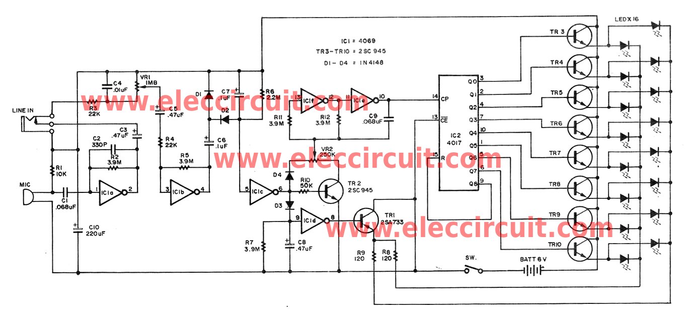
VOX is a voice-controlled switch commonly used for microphones, serving as a replacement for the traditional switching button. The actuating threshold is adjusted through the volume potentiometer. The VOX (Voice Operated Switch) circuit functions by detecting sound levels and activating...
The temperature sensor U2 needs to be located next to the item being monitored. As the temperature increases the motor duty cycle will increase. D1 and R2 are optical components, they only need to be installed for a visual...
Crystal 80mW FM transmitter circuit diagram of the production The Crystal 80mW FM transmitter circuit is designed to generate frequency modulated (FM) signals suitable for short-range audio transmission. This circuit primarily consists of a crystal oscillator, which serves as...
Individuals seeking a distinctive gift for Christmas and New Year may find this project appealing. Certification of this project will undoubtedly create a preference for it. The project in question appears to be a creative endeavor aimed at providing a...
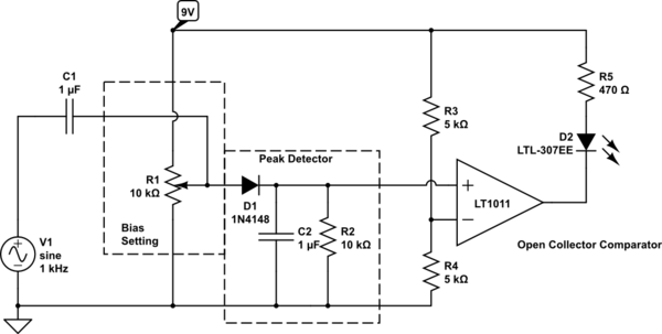
Control an LED with an audio signal; however, the output signal is only 150 mV peak-to-peak (with a 150 mV positive offset). It is understood that a higher voltage than 0.6 V is required to activate the transistor, leading...