
Precision bright light control circuit diagram

The precision bright light control circuit utilizes a Wheatstone bridge configuration to achieve stable performance under varying environmental conditions. The two-arm Wheatstone bridge, composed of resistors R1, R2, R6, and the photosensitive resistor R5, allows for precise measurement of light intensity.
In this configuration, R1 and R2 are fixed resistors, while R5, the photosensitive resistor, changes its resistance based on the ambient light level. R6 serves as a reference resistor. The balance of the bridge is affected by the resistance change of R5 as light levels fluctuate, which can be monitored through an output voltage signal.
This output can be used to control additional circuitry, such as dimming lights or activating alarms based on predefined light thresholds. The circuit's design ensures that it remains unaffected by variations in the power supply voltage, which is critical for maintaining consistent operation in different environments. Additionally, the compensation for ambient temperature changes allows for reliable performance across a range of conditions, making this circuit suitable for applications in both indoor and outdoor lighting control systems.
Overall, this precision bright light control circuit is an effective solution for applications requiring accurate light detection and control, ensuring optimal performance regardless of external factors. As shown in the circuit as a precision bright light control circuit, its work is not affected by the power supply voltage and ambient temperature. Resistors R1, R2, R6 and phot osensitive resistance R5 together constitute two-arm Wheatstone bridge.
Related Circuits

The circuit schematic diagram of a fan speed control system that activates only when necessary. When the transistor heats up, the fan will automatically turn on. The fan speed control circuit operates based on the temperature of the transistor, utilizing...

This circuit is particularly applicable to digitally controlled systems in robotic and X-Y positioning applications. By operating from a 5-V logic supply, it eliminates the need for additional motor drive supplies. The tachless feedback mechanism saves both space and...

This circuit should only be attempted by individuals with a strong understanding of electronic devices. It is connected to a main power source (220V) and poses a risk of high electrical shock. This circuit operates at a mains voltage of...
The receiver input circuit is powered by a 60Ω generator. A low-pass filter is employed to permit the entire frequency range while maintaining uniform sensitivity. The receiver input circuit is coupled with a transmitter inductive component (Ri = 60Ω)....
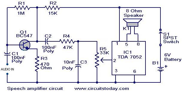
This circuit can be housed within a box containing a speaker to create a convenient microphone amplifier. It is suitable for use by teachers, guides, lecturers, and others in crowded or noisy environments. The design is based on the...

The difference between the amplified signals is utilized to establish the bias for Q1 and Q2 current channels. Q1 regulates the gate-source voltage (VGS) to the necessary level corresponding to the circuit's input and potential output. A 2000 pF...