
RGB LED Controller with PIC18F25K20
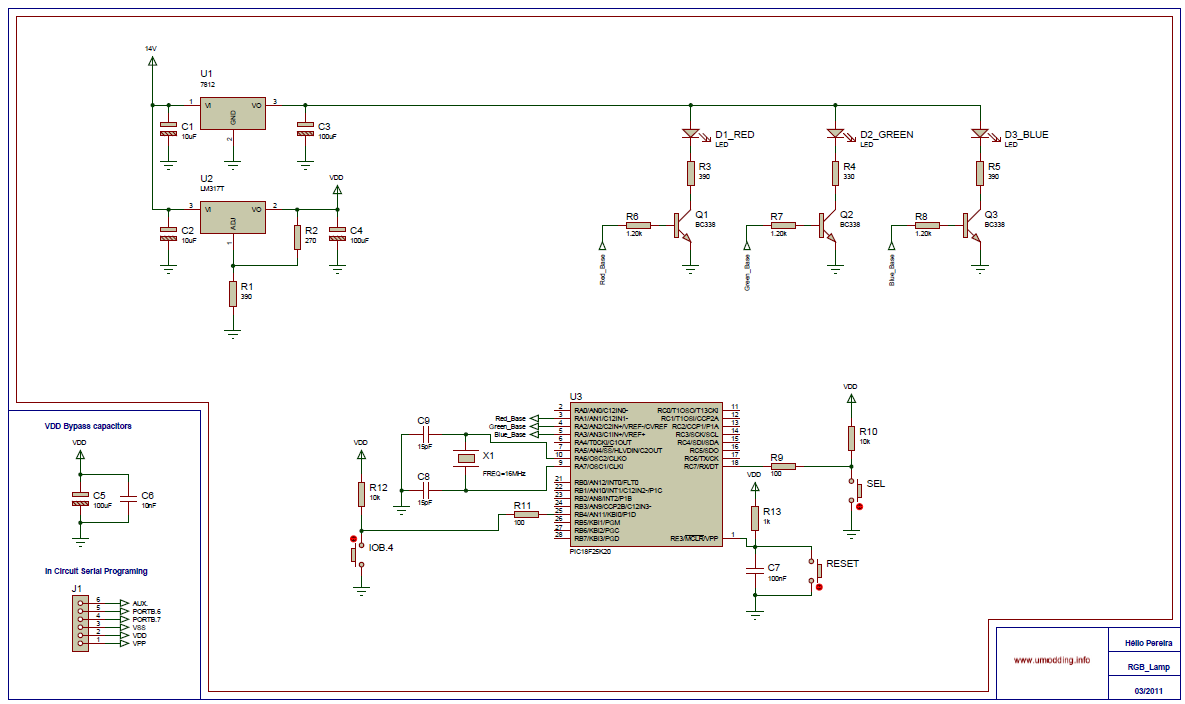
The project utilizes a Piranha Super-flux RGB LED configured as a common anode device, interfaced with a PIC18F25K20 microcontroller. The primary objective is to generate various color combinations through two operational modes: an automatic mode that cycles through a pre-defined sequence stored in the microcontroller's memory and a manual mode that allows the user to select from seven distinct colors.
The RGB LED is controlled using Pulse Width Modulation (PWM) techniques. The PIC18F25K20 microcontroller is equipped with only two hardware PWM outputs. To achieve control over all three colors (Red, Green, and Blue) of the RGB LED, software PWM techniques are implemented. This is accomplished by leveraging TIMER0 to generate the necessary timing signals for PWM control, effectively allowing the microcontroller to simulate additional PWM outputs.
For user interaction, push buttons are employed to switch between the automatic and manual modes, as well as to choose specific colors in manual mode. A significant challenge arises from the mechanical characteristics of push buttons, which can lead to erratic state transitions due to bouncing. This bouncing results in multiple high and low states being detected during a single press, potentially causing unintended behavior in the circuit.
To mitigate this issue, a software-based de-bouncing algorithm is implemented. This approach avoids additional costs associated with hardware solutions, such as RC delay circuits or Schmitt triggers. The software algorithm ensures that only a clean, single transition is recognized for each button press, thereby enhancing the reliability of user inputs and ensuring smooth operation of the color selection functionality.
Overall, the design emphasizes efficient use of microcontroller resources, effective user interaction through intuitive controls, and robust handling of mechanical switch behavior, making it suitable for applications requiring dynamic RGB color control.In this project it was used the ?Piranha Super-flux RGB? Led of common anode, and the PIC18F25K20, in order to generate combinations of colors. It has two function modes, automatic that generate the color sequence that is stored in the ?C memory, and the manual mode in which you can select one of the seven possible colors. The control of the RGB led is made with PWM(Pulse With Modulation), because PIC18F25K20 only have 2 PWM outputs (Hardware), I did the PWM by software to have 3 PWM outputs for that I use TIMER0 and for the Manual mode I use IOC(interrupt on change).
In this project I use push buttons to change between modes and to change the colors. But if we use the button as in the circuit (1) we have a problem. The problem with this configuration, due to the mechanical nature of any switch that may contains spring return action of some kind, there won?t be a clean transition from a state to another, but instead there will be a series of high and low states spikes. To solve that problem we have to implement a de-bouncing system, it can be done by hardware or software.
We can use a RC delay circuit or it can be done with a schmitt trigger, but both ways will increase the price. So I done by software the de-bounce. 🔗 External reference
Related Circuits

The WS2512-TR1G is a Wide-band Code Division Multiple Access (WCDMA) Power Amplifier (PA) designed as a fully matched 10-pin surface mount module, specifically developed for WCDMA handset applications. This power amplifier module operates within a frequency range of 1920-1980...

Light emitting diodes are advantageous due to their smaller size, low current consumption and catchy colours they emit. Here is a running message display circuit wherein the letters formed by LED arrangement light up progressively. Once all the letters...
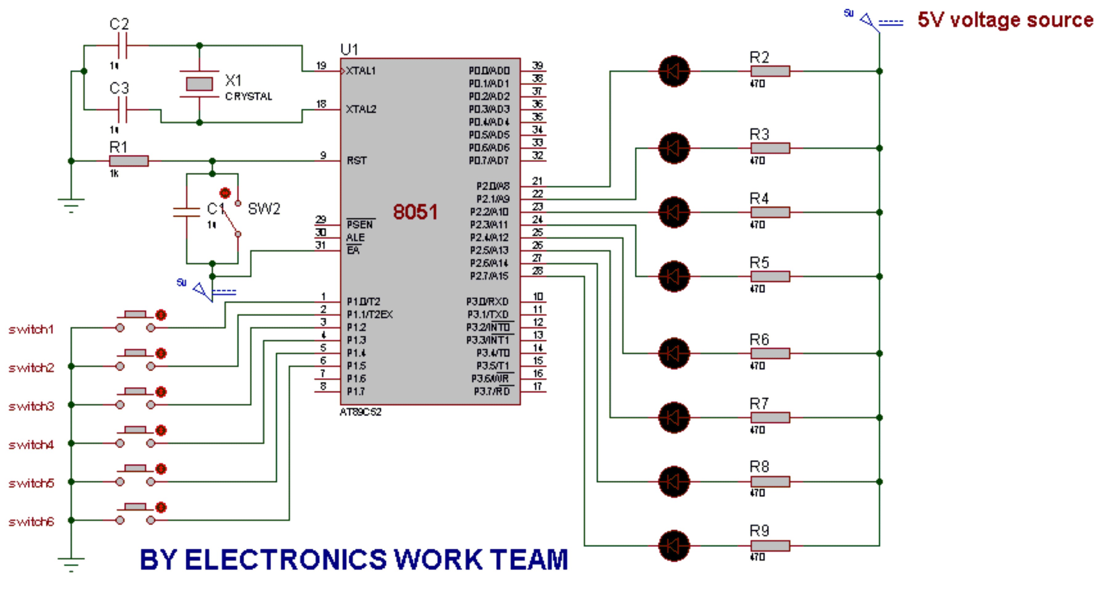
This post discusses the fundamental operation of the 8051 microcontroller using LEDs. The LEDs are connected to the P2 port, while six switches are connected to the P1 port of the 8051. By pressing various switches, the LEDs will...
The L29 Stepper Motor Controller IC facilitates the control of four drive signals for two bipolar and four unipolar footfall motors in a microcomputer-controlled appliance. It allows for motor operation in half-step, full-step, and wave drive modes, utilizing switch-mode...

VCR Camera Video Detector Switch Controller Circuit. This video detector switch controller circuit utilizes the video output from a VCR or camera to... This circuit functions as a video detector switch controller, designed to manage the video output from a...
In the circuit below, 60 individual LEDs indicate the minutes of a clock, while 12 LEDs represent the hours. The power supply and timing circuitry are similar to those described in the previous 28 LED clock circuit. The minute...