
Electric blankets circuit

The electric blanket circuit operates by regulating the voltage supplied to the heating element through a simple switch mechanism. The primary switch, designated as S, has two operational states: full and half. In the full position, the switch connects the heating element directly to the mains supply of 220V, enabling maximum heating output. This state is suitable for rapid warming of the blanket to achieve a high-temperature environment.
When a lower temperature is preferred, the switch is toggled to the half position. This action routes the supply voltage through a half-wave rectifier diode, labeled as VD1. The half-wave rectifier allows only one half of the AC waveform to pass, effectively halving the voltage supplied to the heating element. This reduction in voltage results in decreased power to the heating wire, thereby lowering the temperature of the blanket.
The circuit design may also include a status indicator, which visually communicates the current heating state to the user. This feature enhances usability by providing real-time feedback regarding the operation of the electric blanket. The heating element itself is typically composed of resistive wire, which converts electrical energy into heat through the principle of Joule heating.
Overall, the described electric blanket circuit is a straightforward yet effective solution for temperature control, allowing users to customize their comfort level with ease. The integration of a half-wave rectifier and a simple switch mechanism provides a reliable means of adjusting heat output while maintaining user safety and convenience.Electric blankets circuit controlled by the switch S, when the switch S full, 2ZOV entire supply voltage electric wire heating, high temperature state. When the required time t o low temperatures, the switch is turned Lo half, after the Philippine electricity - half-wave rectifier diode VD1, voltage is reduced by half, for the low-temperature state can be the root user. According to their needs .LI;: D heated display status .
Related Circuits
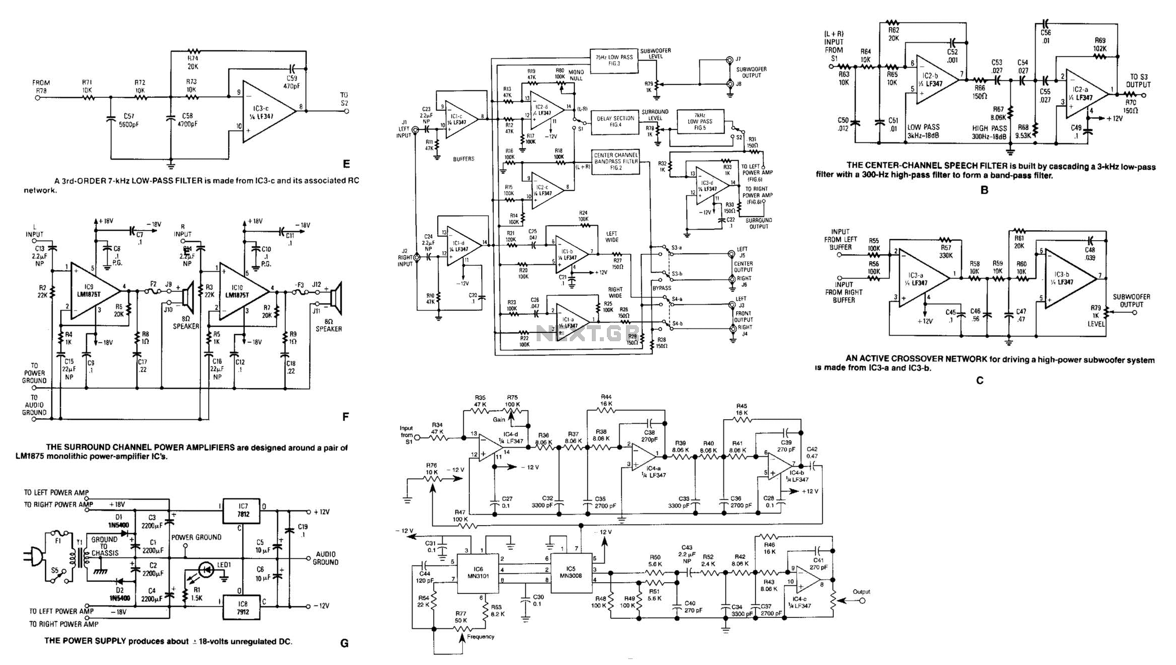
Referring to the simplified schematic in A, the audio frequency generator (AFG) consists of 10 relatively simple circuit elements. IC1-c and IC1-d are configured as unity-gain non-inverting buffer amplifiers. The summing amplifier, IC2-c, combines equal amounts of the left...
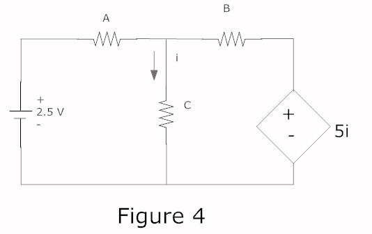
In a complete circuit, there are two types of elements: active and passive elements. Active elements generate energy, while passive elements dissipate energy. Examples of passive elements include resistors and capacitors. In electronic circuits, active and passive components serve distinct...
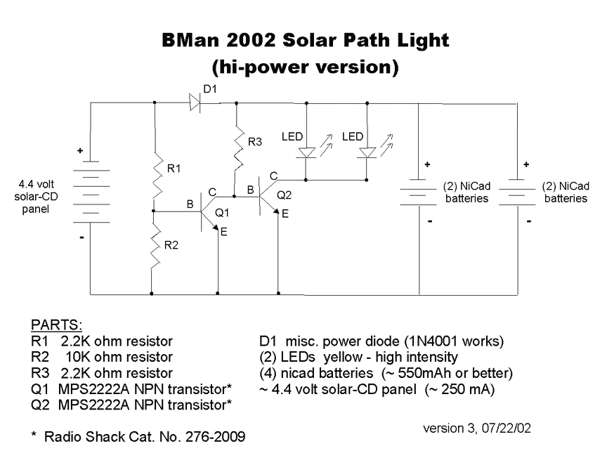
The completed Solar CD Two LED circuit is presented with components labeled to correspond with the schematic. Although the soldered circuit may appear different from the schematic, the connections remain consistent, which is crucial. To transition from the schematic...
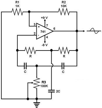
This circuit generates a sine wave using a single operational amplifier (741). The feedback loop of the op-amp includes a twin-T filter connected between its output and inverting input. Positive feedback for oscillation is provided by resistor R2. The...
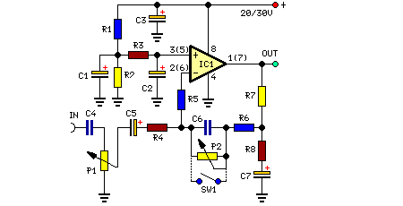
This preamplifier is designed to interface with CD players, tuners, tape recorders, and similar devices, providing an AC voltage gain of 4 to drive less sensitive power amplifiers. Given that modern Hi-Fi home equipment often comes with small loudspeaker...
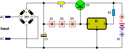
This battery charger operates by continuously charging at maximum current, gradually tapering off as the battery approaches full voltage. The full load current from the supply transformer and rectifier section is 4.4A. The current decreases to 4A at 13.5V,...