
Lightning Activated Camera Shutter Trigger

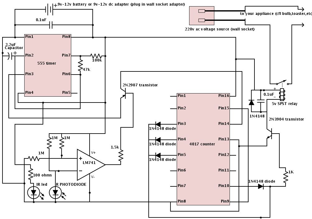
The Lightning Activated Camera Shutter Trigger is designed to capture images of lightning strikes by activating a camera's electronic shutter in response to the sudden burst of light produced by a lightning flash. The core of this circuit typically includes a light sensor, such as a photodiode or a phototransistor, which detects the intensity of light. When a flash is detected, the sensor generates a signal that is processed by a microcontroller or a simple transistor switch.
The circuit can be powered by a battery or an external power source, ensuring that it is portable and can be used in various outdoor conditions. The output from the light sensor is often connected to a comparator circuit, which amplifies the signal and ensures that only significant light changes trigger the shutter. This is crucial for avoiding false triggers from other light sources, such as car headlights or street lamps.
To connect the circuit to the camera, a relay or an opto-isolator is commonly employed. This component allows the circuit to control the camera's shutter without directly interfacing with its electronics, thus preventing any potential damage. The relay should be rated for the voltage and current specifications of the camera's shutter release mechanism.
Additional features may include adjustable sensitivity settings to cater to different lighting conditions and a delay mechanism to allow for multiple captures in quick succession after the initial trigger. The overall design should be compact and robust, suitable for outdoor use where environmental factors may come into play. Proper housing for the circuit may include weatherproofing to protect sensitive components from moisture and debris.
Overall, this circuit serves as an effective tool for photographers aiming to capture the fleeting moments of lightning, combining simplicity in design with functionality tailored for specific photographic needs.Lightning Activated Camera Shutter Trigger. This picture was taken using the circuit. This circuit is used to trigger a camera`s electronic shutter circuit when a flash of. 🔗 External reference
Related Circuits
The circuit uses a 555 timer wired as an astable oscillator and powered by the emitter current of the BC109C. Under dry conditions, the transistor will have no bias current and be fully off. As the probes get wet,...

A typical circuit for welding equipment is illustrated in the following circuit diagram. The turn-on delay can be accurately controlled with Potentiometer P2, allowing for effective discharge management. The welding equipment circuit typically incorporates several key components to ensure proper...
Figure a illustrates a multivibrator circuit capable of generating a square wave signal. Figure b depicts a flip-flop circuit that utilizes the falling edge of the input signal to produce a trigger pulse signal. Figure c represents a monostable...
Flash slaves are used when you need to supplement one flash unit with one or several more. This slave trigger simply triggers those other units. It does this by "seeing" the first flash (using a phototransistor) and triggering the...
The camera and shutter control system is entirely self-contained, designed for automatic photo capture at set intervals. It is particularly suited for Kite Aerial Photography but can also be utilized with RC planes and other applications. The LMC555 CMOS...
The schematic is provided below. It is recommended to construct it in three distinct sections, similar to the method demonstrated. The 555 timer circuit: connect pin 2 to pin... The schematic outlines a circuit design utilizing a 555 timer, a...