
shutter

The described camera and shutter control system can be implemented in various electronic applications beyond Kite Aerial Photography. The use of the LMC555 CMOS Timer IC as an astable oscillator is a practical choice for generating precise timing intervals, enabling the automation of photography without the need for complex programming or additional power sources. This simplicity allows for easy integration with other devices, such as drones or remote-controlled vehicles.
The construction of the circuit using the dead bug method presents a lightweight and compact solution, making it suitable for aerial photography applications where weight is a critical factor. By utilizing low-leakage capacitors and ensuring the 555 timer is of the CMOS variety, the reliability and accuracy of the timing mechanism are enhanced.
For applications requiring varied timing intervals, the flexibility to adjust resistor and capacitor values offers a customizable solution. The inclusion of a trimpot allows for fine-tuning, accommodating different photographic needs and conditions. Furthermore, the ability to connect multiple timers provides scalability for more complex setups, such as multi-camera arrays.
The integration of the circuit within the camera itself, as suggested for surface mount components, can lead to a neater assembly and improved aesthetics, making it more appealing for consumer applications. Additionally, the detailed instructions available through dedicated electronics websites facilitate the assembly process, ensuring that even those with limited experience can successfully replicate the design.
Overall, this camera and shutter control system exemplifies an efficient and effective approach to automating photography, suitable for a wide range of applications while maintaining ease of use and assembly.The camera and shutter control are completely self contained and can be used in any situation where you would like to take a number of photos automatically at a set interval in time. In this case it is for Kite Aerial Photography, but I have used this camera with an RC plane as well.
I am sure you will come up with many more interesting applicatio ns for this camera. I look forward to hearing how you use this design. The inexpensive LMC555 CMOS Timer IC can be configured as an astable oscillator. That is a fancy way of saying that it can close a switch every few seconds, open it again and repeat until the camera`s memory is full. In this case, at a resolution of 640x480, that is 180 pictures, or 15 minutes of photography. A more sophisticated intelligent shutter control which still requires no external power and only 2 wires to connect to this camera or any camera with similar features can be built using Texas Instruments MSP430 line of low power microprocessors.
I have recently constructed a controller for the GoPro HD Hero camera. GoPro HD Hero Controller. As the Mustek Mini 3 camera shutter is a simple switch (not all cameras are), this simple circuit will operate the camera automatically, taking a picture every 5 seconds, from the time it is turned on. It only takes one IC, 3 resistors, and a capacitor to build it. The power is stolen from the shutter circuit of the camera. The 555 IC must be the CMOS type as it is being powered by the camera itself. The capacitor should be of a low leakage type, or the actual time will be longer than the calculated value.
There is nothing critical about the construction. For minimum simplicity and weight, I used the dead bug construction method of flattening the IC and wiring the parts together without a circuit board. The resulting circuit was then be taped to the outside of the camera. Different timing can be arranged by changing the value of R1 or C1. For a 15 second timer, change R1 to 3 Megohms. If you find that the time is shorter or longer than expected due to the capacitor leakage, adjust R1 accordingly.
If you want different times, you could use a miniature trimpot in place of the fixed resistor, or build multiple copies of the timer and use a jack and plug arrangement to connect them to the camera. If you change C1, you should adjust the value of R2 as the combination determines the time the shutter switch is closed.
Too short a time and a picture will not be taken. Too long a time will waste battery power. Rob Paisley has created a very informative web page with lots of simple circuits using the 555 Timer IC. His Astable Oscillator Calculator will help you choose the correct values for your shutter control. The circuit could also be built with surface mount components and would then fit inside the camera by turning the battery the other direction and placing the new parts over the shutter switch.
The RC Creative Electronics web site shows step by step how to open the Mustek Mini 3 camera and wire a connection to the shutter control. The red wire goes to positive. The black wire goes to the negative connection on the timer circuit. Hot glue is used to seal the wires coming out of the camera to take any strain off the solder connection.
The parts are taped to the top of the camera with transparent shipping tape. The complete camera and timer circuit weighs less than 40 grams (1. 4 oz). It`s ugly, but it works great. I have also dripped a blob of hot glue on the edge of the lens in order to prevent it turning away from the distant setting and ruining the focus of the pictures. It is easy to accidentally turn the lens when setting up the camera and attaching it to the kite string.
Turn on the camera as usual. You have 5 seconds to select the mode you wish to use. I usually use the 640x480 mode, which requires pressing the mode switch twice to select the smallest size. I have also used the 1600x1200 size which is the d 🔗 External reference
Related Circuits
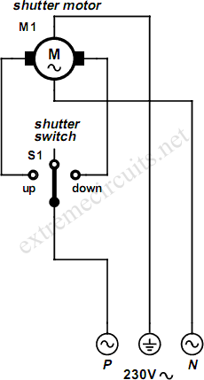
An electrically operated rolling shutter typically features a standard control panel equipped with a three-position switch that allows for up, down, and stop functions. The electrically operated rolling shutter system is designed to provide convenient control over the opening...
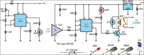
The IR detector (IC3) controls an LM 7555 CMOS timer (IC2) operating in monostable mode. When the beam is interrupted, IC2 is triggered, and its pin 3 output goes high for approximately half a second. This action extinguishes LED1...
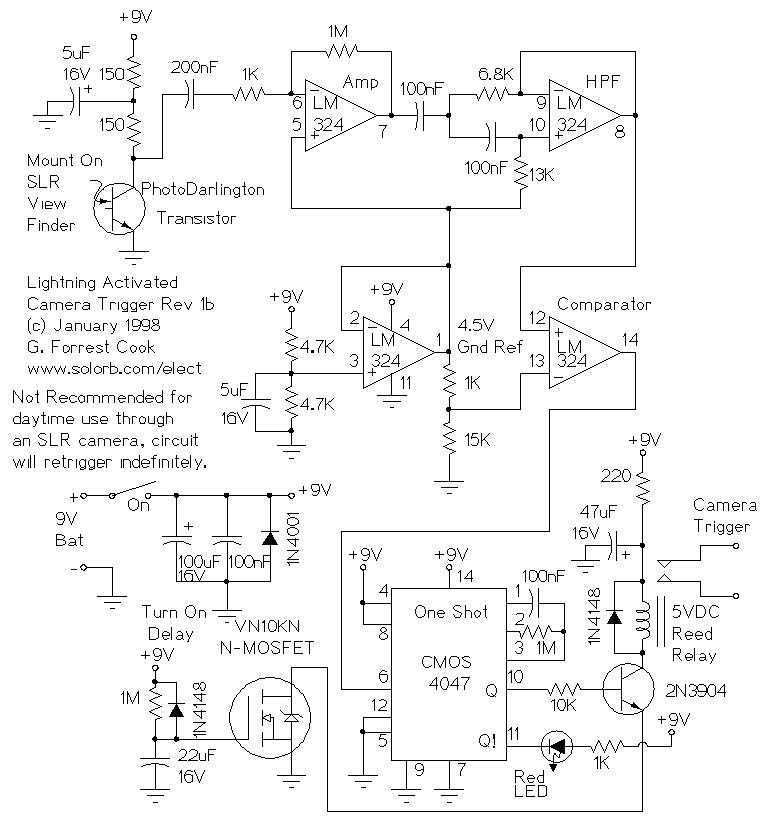
This circuit is used to trigger a camera's electronic shutter circuit when a flash of lightning is present. This circuit would also work for photographing fireworks displays or other events involving flashes of light. More: In a nutshell, the...
The most essential accessory for astrophotography, after a camera, telescope, and mount, is a remote shutter release to minimize vibration. A remote control is even more advantageous if it can trigger a series of exposures at preset intervals and...
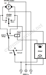
To automate the opening and closing of a rolling shutter using a time-controlled switch, additional wiring will be necessary. To implement an automated system for a rolling shutter, a time-controlled switch can be utilized to manage the operation of the...
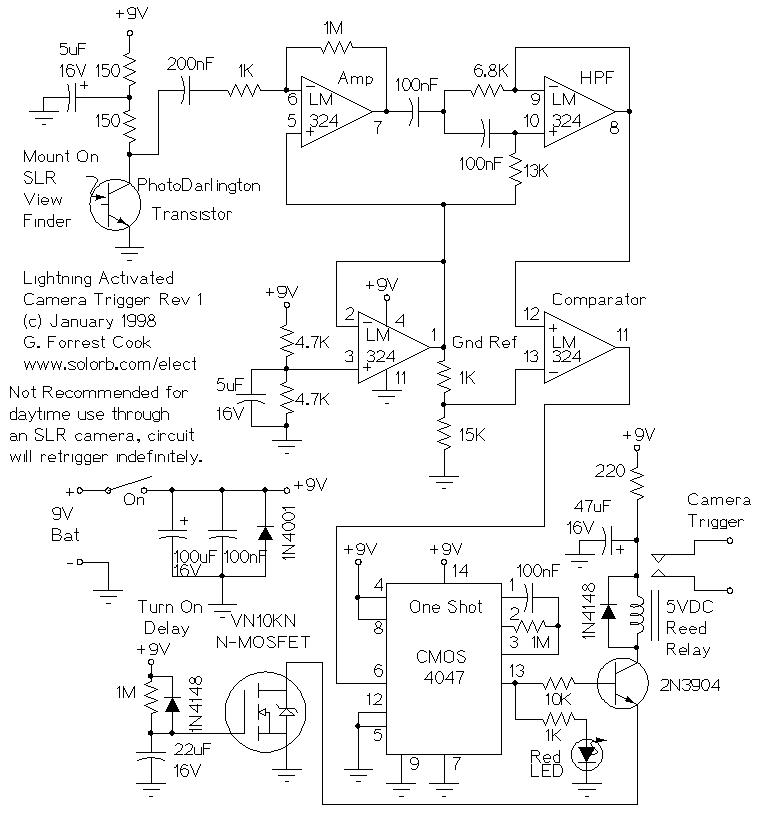
Lightning Activated Camera Shutter Trigger. This picture was taken using the circuit. This circuit is used to trigger a camera's electronic shutter circuit when a flash occurs. The Lightning Activated Camera Shutter Trigger is designed to capture images of lightning...