
Battery Guard for Emergency Lights

An emergency light system typically consists of several key components: a light source, a rechargeable battery, a charging circuit, and an automatic control mechanism. The light source is usually an LED or incandescent bulb that provides illumination when the main power supply is interrupted.
The rechargeable battery stores energy to power the light source during outages. Common battery types include nickel-cadmium (NiCd), nickel-metal hydride (NiMH), or lithium-ion (Li-ion), chosen for their ability to hold charge and provide reliable performance.
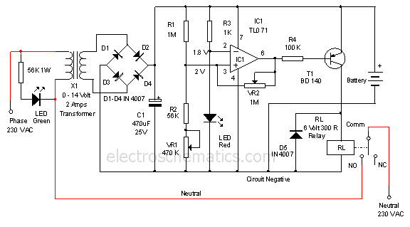
The charging circuit is responsible for maintaining the battery's charge when the main power is available. This circuit ensures that the battery is adequately charged without overcharging, which could reduce its lifespan. It typically includes a transformer, rectifier, and voltage regulator to convert AC mains voltage to a suitable level for charging the battery.
The automatic control mechanism detects power failure and activates the light source. This can be achieved using a relay or a solid-state switch that monitors the input voltage. When the mains power drops below a certain threshold, the control circuit engages the light source, providing immediate illumination.
Overall, an emergency light system is essential for safety in various environments, including residential, commercial, and industrial settings, ensuring visibility and guidance during power outages or emergencies.As the name implies,emergency light is a source of light available during an emergency.It is an automatic system in which a rechargeable battery operated l.. 🔗 External reference
Related Circuits
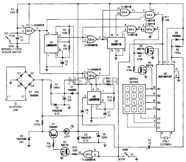
This system will alert individuals by automatically dialing a programmed phone number. It operates by monitoring an open-loop or closed-loop sensor switch located in the protected area. When the sensor detects an issue, such as a break-in, fire, heating...
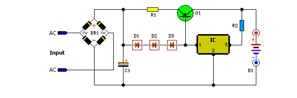
The above pictured schematic diagram is just a standard constant current model with a added current limiter, consisting of Q1, R1, and R4. The moment too much current is flowing biases Q1 and drops the output voltage. The output...
Unlike many units, this battery charger continuously charges at maximum current, tapering off only near full battery voltage. In this unit, the full load. This battery charger is designed to operate with a continuous charging mechanism, maintaining the maximum current...
This is a 12-volt lead-acid automatic battery charger that stops the charging process once the battery reaches a full charge. This feature prevents overcharging. The 12-volt lead-acid automatic battery charger is designed to efficiently charge lead-acid batteries while ensuring safety...
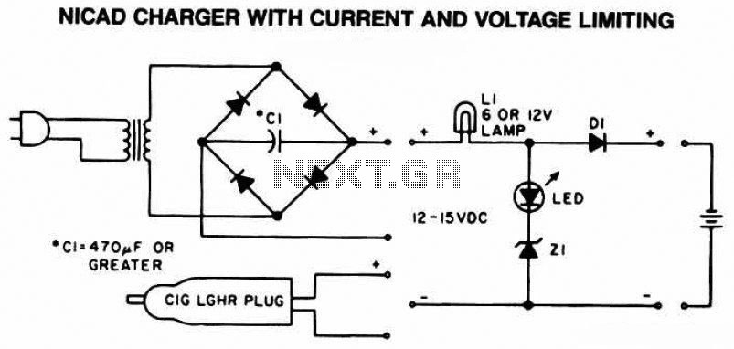
The following diagram is the schematic of a Ni-CAD battery charger circuit, which includes current and voltage limiting features to extend the battery's lifespan. The lamp L1 will illuminate brightly, and the LED will be off when the battery...
The circuit utilizes a 555 timer configured as a multivibrator, where the oscillation frequency is determined by resistors R1, R2, and capacitor C1. The frequency formula is given by fo = 1.443 / ((R1 + R2) * C1). The...