
5G169 holiday lights integrated circuit

The circuit operates by first converting the alternating current (AC) from the VDI source into direct current (DC) using a full-wave bridge rectifier comprised of four diodes, designated as VD4. This rectification process results in a pulsating DC output that is suitable for powering multiple lighting elements. The output voltage is smoothed and regulated by the combination of components R1, R2, VD5, and VD6. Resistors R1 and R2 help in current limiting and voltage division, while VD5 acts as a simple diode to ensure current flows in the correct direction. VD6 is specifically utilized as a voltage regulator, maintaining the output voltage at a stable 6V DC despite variations in the load or input voltage.
Capacitor C1 plays a crucial role in filtering the pulsating DC output, effectively reducing ripple voltage and providing a more stable DC supply. The ripple frequency, which is double the input AC frequency, is noted to be 100Hz. The circuit includes a mechanism for synchronization, achieved through resistor R4, which injects a signal into the power supply manifold to ensure consistent operation across the circuit.
The operation of the circuit can be controlled using switch SB, which toggles between forward and reverse modes. In the forward mode, the switch is open, allowing current to flow in a designated direction. Conversely, closing the switch reverses the current flow, altering the operation of the connected lights. The configuration detailed in Figure 2-102 outlines the forward loop, indicating the pin outputs from 9 to 12, which are integral to the circuit's functionality. The dashed lines in the figure represent the varying arc light levels, which can be adjusted over a period ranging from 100 milliseconds to 5 seconds, providing flexibility in light intensity and timing for the application.AC by VDI ~ VD4 full-wave bridge rectifier output pulsating DC power for four lights. Rl, R2, VD5 simple composition and VD6 regulator circuit, Cl filtered output by about 6V D C power supply manifold. VD6 here isolators, so to get across R2 6V full-wave pulsating direct current voltage ripple frequency of the alternating current to twice that of 100Hz, 100Hz for this signal by R4 injection manifold 8 feet as a synchronization signal. FIG. SB is forward and reverse control switch, SB open cycle is positive; SB closed reverse circulation. Figure 2-102 is the forward loop convolutions 9 to 12-pin output, the dashed line indicates the arc light levels change, period r adjustable range lOOms ~ 5s.
Related Circuits
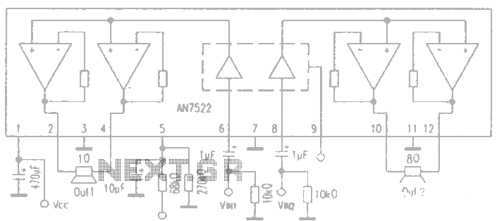
AN7522 is a Panasonic stereo audio amplifier IC that delivers an output power of 3W at 8 ohms. It features a standby function, low static power consumption, and reduced noise levels, requiring fewer external components for stable operation. This...
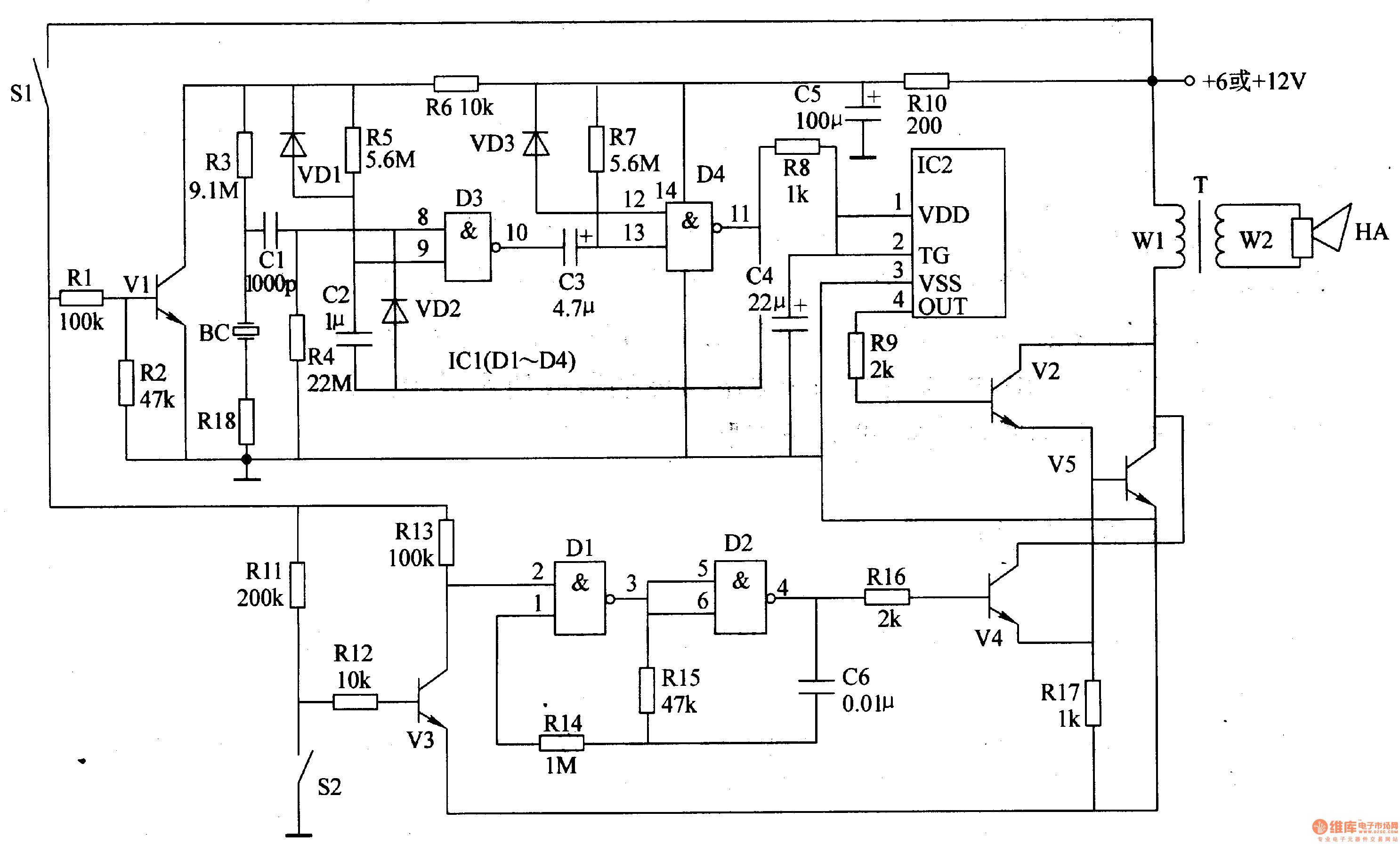
The motorcycle anti-theft alarm circuit consists of several components, including the anti-theft detection circuit, the control circuit, the sound generator, the audio oscillator, and the power amplifier output circuit, as illustrated in figure 7-91. The anti-theft detection circuit is...

This circuit generates a siren sound when switch S1 is pressed. The sound frequency increases as capacitor C1 charges, and when switch S1 is released, the frequency decreases as capacitor C1 discharges. The circuit operates on a simple principle of...
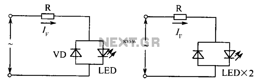
The circuit operates effectively even when the polarity of the voltage or the power supply is reversed. It functions with DC drives similar to AC drives, utilizing a current limiting resistor R. The value of this resistor is determined...

A pH electrode measures hydrogen ion (H+) activity and generates an electrical potential or voltage. The operation of the pH electrode is based on the principle that an electric potential develops when two liquids of different pH come into...
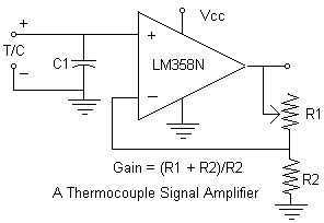
Continuing with the thermocouple interface concept, the next step is to amplify the TC's millivolt signal into a more readable analog voltage, on the order of 0 to 5VDC. This simple circuit fits the bill. The LM358N is a...