
Line Following Robot circuit

The described circuit operates a robotic system utilizing GM3 motors, which are typically rated for higher voltages but are limited to 5V in this configuration to manage speed and control. The power supply is critical, as the motors must be driven at a controlled voltage to prevent excessive speed that could compromise maneuverability and safety.
The line-following capability of the robot is facilitated through the use of line detectors that communicate with relay switches. These relays toggle based on the input status from the detectors, allowing for precise control of motor direction. Specifically, the left line detector is configured to activate the right motor, while the right line detector activates the left motor. This cross-activation is essential for maintaining the robot's trajectory along a designated path.
Moreover, the obstacle detection system plays a significant role in enhancing the robot's operational capabilities. By utilizing a dedicated set of inputs on the line-following chip, the circuit can dynamically enable or disable functionalities based on the presence of obstacles. The second set of inverters, which are continuously grounded, ensures that the obstacle detection mechanism is always active, allowing for real-time adjustments to the robot's navigation strategy.
This design emphasizes the importance of voltage regulation, motor control, and sensor integration in creating an effective and responsive robotic system. Proper attention to these elements ensures that the robot can navigate its environment effectively while adhering to safety constraints.The motors will be driven from the full source voltage, so make sure this isn`t going to make your robot too fast! Firebot has GM3 motors driven with a 9V battery, however the circuit differed and the motors were only driven by 5V from the voltage regulator.
The line detectors drive the relays on or off dependant upon their status, remember that t he left line detector should drive the right motor and vice versa. The obstacle detector enables/disables the inputs on the line following chip. This is made possible by the fact that the chip has two sets of inputs, both with their own enables. The obstacle detector uses the second set of invereters which is grounded (enabled) constantly. 🔗 External reference
Related Circuits
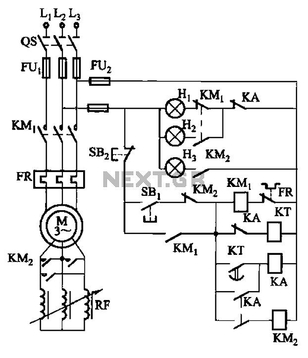
The circuit depicted in Figure 3-165 utilizes a time relay (KT) for controlling the start-up time. Indicator light Hi serves as the power indicator, H2 is designated for the start lights, and H3 functions as the running lights. The circuit...
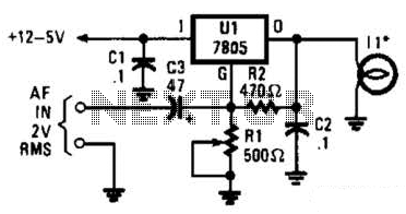
In the visible-light transmitter, a 7805 voltage regulator is configured in a variable-voltage setup, with an audio signal input to modulate the output voltage. The modulated output voltage is utilized to transmit information through an incandescent lamp. The visible-light transmitter...

Circle i represents a two-phase grid connection line for an AC technology turbine shed, which consists of two lines. A voltage is generated between Ri through a Buck converter, with components R1 and R3 dividing the output. The sampled...
This simple circuit allows the use of an oscilloscope as a Time Domain Reflectometer (TDR). The operation involves sending a pulse down a cable and observing the resulting reflections. The circuit design for utilizing an oscilloscope as a Time Domain...
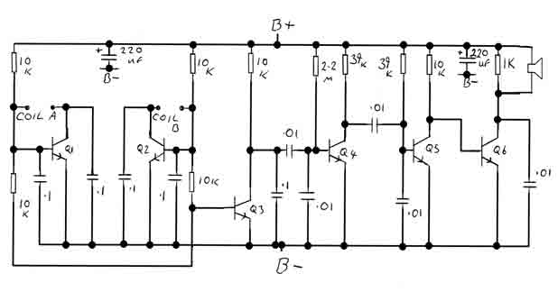
By adjusting the oscillators so their frequencies are very nearly the same, the difference between them is made audible as a beat note. This beat note changes slightly when the search loop is moved over or near to a...

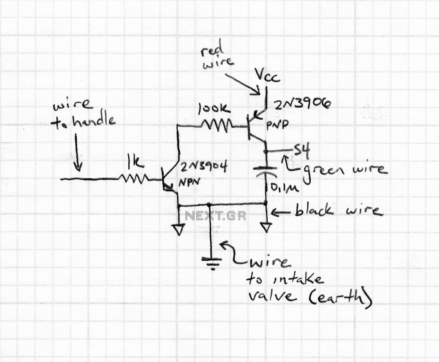
This is a car alarm simulator that uses an LED as a simulation output. This simple circuit can indicate whether a car is running by detecting the voltage difference when the car is on and off. When the car...