
Simple Circuit to Turn your Oscilloscope into a TDR

The circuit design for utilizing an oscilloscope as a Time Domain Reflectometer (TDR) involves several key components and configurations to accurately measure and visualize signal reflections in transmission lines. The primary function of a TDR is to assess the integrity of a cable by sending a fast electrical pulse and analyzing the reflections caused by impedance mismatches along the cable.
To construct this circuit, a pulse generator is required to create the initial signal pulse. This pulse is typically a fast rise-time square wave, which can be generated using a 555 timer IC or a dedicated pulse generator module. The output of the pulse generator is connected to the input of the transmission line or cable under test.
The cable should be terminated at the far end with a known impedance to facilitate accurate measurement of reflections. Commonly, a 50-ohm or 75-ohm termination is used, depending on the specific application and the characteristics of the cable. If the termination is not matched to the cable impedance, reflections will occur, which can be analyzed by the oscilloscope.
The oscilloscope is connected to the same point as the pulse generator, typically through a suitable probe or attenuator to prevent loading effects that could distort the measurements. The oscilloscope is set to trigger on the leading edge of the pulse, allowing it to capture and display the waveform as it travels down the cable and reflects back.
The resulting waveform displayed on the oscilloscope will show the initial pulse followed by any reflections. The time delay between the original pulse and the reflected signals can be used to calculate the distance to the point of reflection, providing insights into the location of faults or discontinuities within the cable.
In summary, this circuit effectively transforms an oscilloscope into a TDR by utilizing a pulse generator, a transmission line, and an oscilloscope to analyze signal reflections, thereby enabling the detection of cable integrity issues. Proper calibration and setup are essential for obtaining accurate measurements and reliable results.This simple circuit allows you to use your oscilloscope as a Time Domain Reflectometer (TDR). This is how it works. Send a pulse down a cable and watch for the. 🔗 External reference
Related Circuits
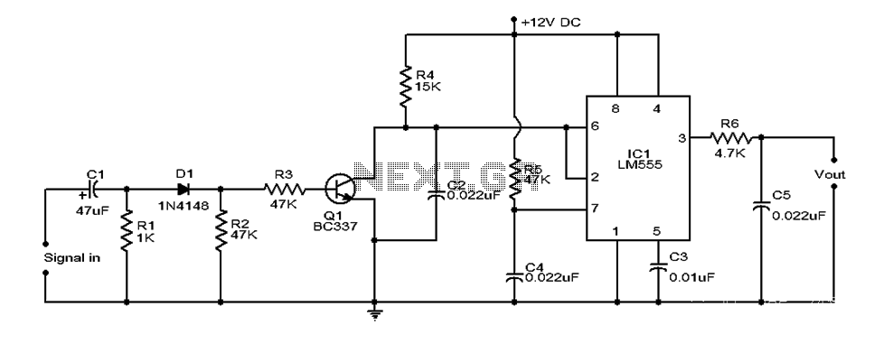
This document provides an overview of a simple circuit diagram for frequency (F and V) voltage conversion. It describes a digital frequency meter circuit primarily based on the LM555 timer IC, which is commonly used in various applications, including...
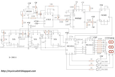
This circuit consists of a temperature sensor, amplifier, voltage-to-frequency (V/F) converter, a three-digit binary coded decimal (BCD) counter, a time base, and seven-segment LED displays. In addition to the 9400 V/F converter, other integrated circuits (ICs) required for this...
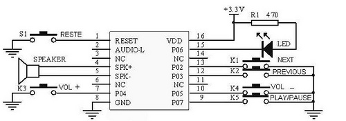
This tutorial focuses on the MP3 mode of the WTV020SD-16P module. With this straightforward circuit, AD4 format music files can be played. A video demonstration of this simple project is available at the end of the article. The project...
The microphone preamplifier circuit design presented in this schematic utilizes the SSM2015 produced by Precision Monolithics Inc. (PMI), which offers high amplification. The SSM2015 is a low-noise, low-distortion integrated circuit designed specifically for microphone preamplification. It features a differential input...
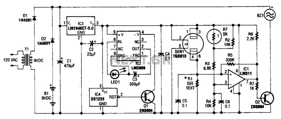
The gas sensor primarily consists of tin dioxide mounted on a ceramic substrate. The sensor's resistance changes based on the concentration of reducing gases present in the air. The depicted circuit is effective for detecting hazardous levels of combustible...
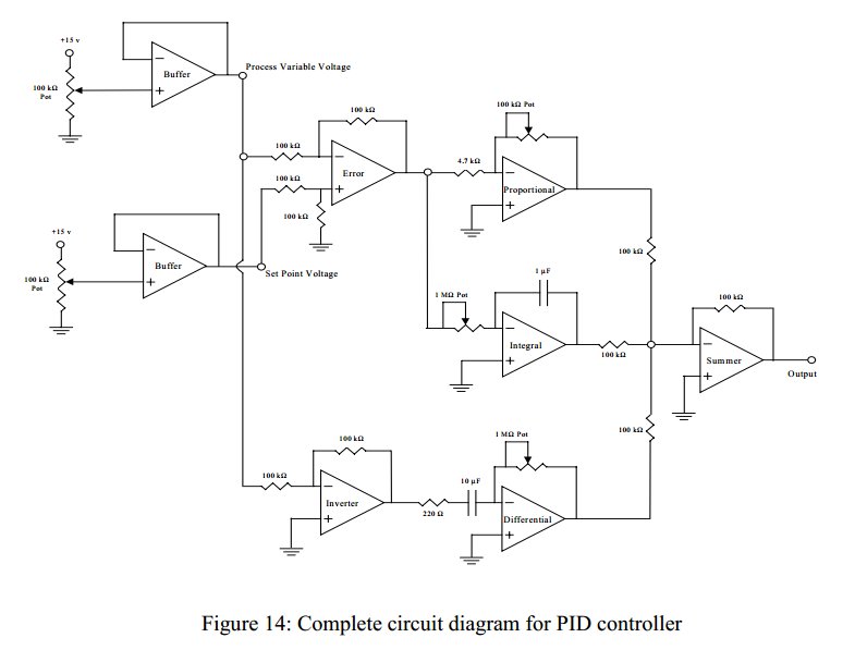
Convert a feedforward operational amplifier PID loop to C code. Assistance is needed for this conversion, as the process is unfamiliar. Input values can be obtained through an ADC, such as voltage or current, but coding a feedforward PID...