
Liquid/Fluid/Water/Float/Tank Level SwitchCircuit using Relay

The liquid level switch circuit is designed to detect the presence or absence of liquid within a tank or container. This type of circuit can be employed in various applications, such as water level control in reservoirs, fluid level monitoring in industrial processes, and float level detection in aquariums or sump pumps.
The basic configuration of a liquid level switch typically consists of a float mechanism, a switch (often a reed switch or a mechanical switch), and a power supply. The float is buoyant and moves up and down with the liquid level. When the liquid level reaches a predetermined point, the float activates the switch, which can then trigger an alert, control a pump, or turn on/off an indicator.
In the schematic diagram, the float is connected to the switch, which is in turn connected to a power source and the load (such as a pump or an alarm). The circuit may include additional components such as resistors, diodes, or capacitors to enhance performance, provide protection against voltage spikes, or filter noise.
For enhanced versatility, the circuit can be designed to operate in both normally open (NO) and normally closed (NC) configurations, allowing for customization based on the specific application requirements. The use of microcontrollers or programmable logic controllers (PLCs) can further improve functionality by enabling more complex control algorithms and integration with other systems.
Overall, this liquid level switch circuit is a fundamental yet essential component in fluid management systems, providing reliable and effective monitoring and control of liquid levels.A simple liquid level switch circuit with diagram and schematic.This can also be used as water level switch,fluid level,float level and tank level switch.. 🔗 External reference
Related Circuits
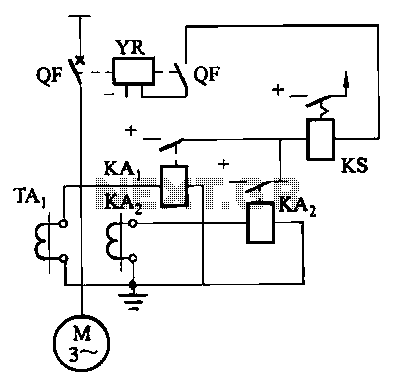
Figure 4-52 (a) illustrates the two-phase wiring for direct current (DC) operation, while Figure 4-52 (b) depicts the two-phase current differential wiring for alternating current (AC) operation. The schematic in Figure 4-52 (a) represents a two-phase wiring configuration suitable for...
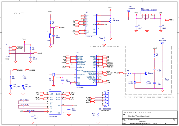
IperCODE is an educational project that enables the construction of a remote control acquisition system utilizing rolling code technology. It allows for the transmission of the received code via an RS232 serial port, the visualization of the code on a...
A circuit that offers visual indication of fluid level in a vessel, with a switchable audible alarm. Example uses would be to monitor the level of water in a bath or cold storage tank. Conductance is the reciprocal of...

This circuit provides a simple and efficient method to draw current from a motorcycle battery to charge a mobile phone. Most mobile phone battery packs consist of three 1.2-volt cells, resulting in a total voltage of 3.6 volts. For...
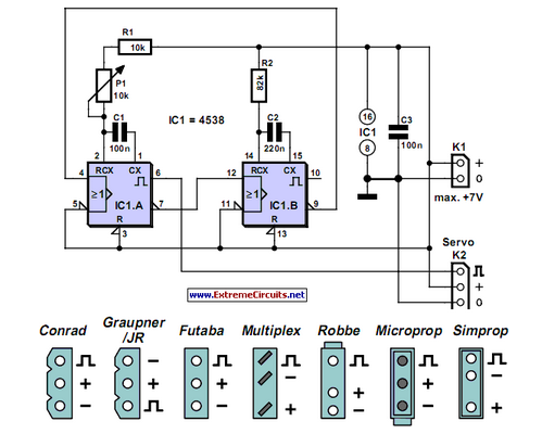
Individuals who frequently work with servos are likely familiar with situations where a servo tester is beneficial. The primary function of a servo tester is to produce a pulsing signal with a variable positive pulse width ranging from 1...
JG series of photoelectric relay circuit. To ensure reliable operation, a Schmitt trigger circuit has been incorporated. These circuits function similarly; when light strikes the photosensitive component, its internal resistance decreases, activating the transistor VT and subsequently energizing the...