
Ni-cad charger

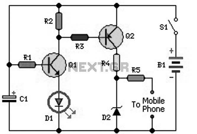
The circuit design incorporates a constant current source that ensures stable operation of the LEDs regardless of variations in supply voltage. The LEDs serve as both indicators and current regulators, providing visual feedback when the circuit is active. The choice of a 15 mA current allows for efficient charging of rechargeable cells, making it suitable for applications involving lithium-ion or nickel-metal hydride batteries.
To create the desired charging current, multiple LEDs can be paralleled; for instance, connecting two LEDs in parallel will result in a charging current of 30 mA, while three will yield 45 mA. This flexibility enables the circuit to accommodate different battery configurations and charging requirements effectively.
The circuit should include a voltage regulator to maintain the supply voltage within the operational range of the LEDs, ensuring they function properly without exceeding their rated limits. Additionally, the use of current-limiting resistors may be necessary to protect the LEDs from excessive current, especially when multiple LEDs are used in parallel.
Overall, this constant current LED circuit presents a practical solution for charging batteries with varying current requirements while providing a clear indication of operation through the illumination of the LEDs. This design is particularly advantageous in portable electronic devices where battery management is critical.This circuit uses constant current LEDs to adjust charging current. It makes use of LEDs that pass a constant current of about 15 mA for an applied voltage range of 2-18 V. They can be paralleled to give any multiple of 15 mA and they light up when current is flowing The circuit will charge a single cell at 15, 30 or 45 mA or cells in series up to the rated supply voltage limit (about 14 V).
Related Circuits
This 3A charger was originally designed to work with small batteries like those used in motorcycles. In principle it can be used to charge car batteries also but will take a lot longer. The charger below charges a battery...
MSP430 microcontroller and I2C-compatible slave peripheral device. Temperature measurement tasks can be accomplished in a variety of ways. The MSP430 microcontroller is a low-power, 16-bit device widely used in embedded systems, particularly for applications requiring efficient power management and precise...
An ideal mobile charger utilizing 1.5-volt pen cells to charge mobile phones while traveling. This charger can replenish a cell phone battery three to four times in locations where AC power is unavailable. Most mobile phone batteries are rated...
A mobile phone charger powered by a solar cell power supply is described. This system utilizes a dual comparator circuit that connects the solar panel to the battery when the voltage at the battery terminal is low and disconnects...
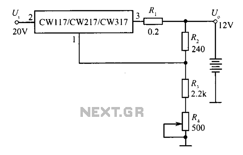
A 12V constant voltage charger is depicted. The power supply circuit shares the same basic design. The resistor R1, valued at 0.2 ohms, serves a limiting function, effectively increasing the internal resistance of the charger, which in turn reduces...
Savings on electricity bills can be achieved by utilizing alternative power sources. The photovoltaic module or solar panel described here has a power output of 5 watts, providing 16.5V under full sunlight conditions, with a current delivery of 300-350...