
LM10 Current Regulator
A current regulator circuit is designed to ensure that a specific current flows through a load, providing stability in applications where current fluctuations could lead to undesirable performance or damage. The circuit typically consists of an operational amplifier (op-amp), a reference voltage source, and a pass element such as a transistor or MOSFET.
In operation, the op-amp compares the voltage across a sensing resistor, which is in series with the load, to a predetermined reference voltage. When the load current increases and the voltage across the sensing resistor exceeds the reference voltage, the op-amp's output will adjust the gate or base of the pass element, reducing the current flow to maintain the desired output. Conversely, if the load current decreases, the op-amp will increase the output to allow more current to flow.
This feedback mechanism allows the current regulator to adapt to changes in load conditions while ensuring that the current remains stable. The design can be applied in various scenarios, including LED drivers, battery chargers, and precision current sources in laboratory settings. Proper selection of components, including the op-amp, pass element, and sensing resistor, is crucial for achieving the desired performance and stability in the current regulation process.Current regulator acts like a load when connected to a voltage source, or in series between voltage source and real load. The main characteristic of a current.. 🔗 External reference
Related Circuits
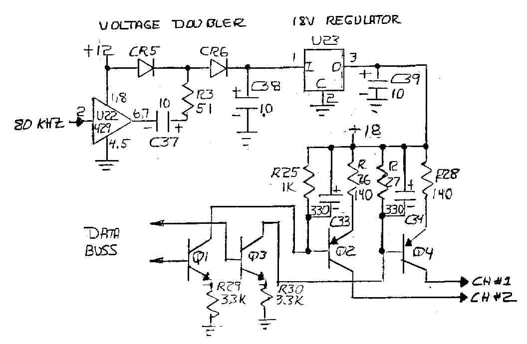
The DSC Sine and DRC Random vibration controller cards feature current sources on the two inputs that provide power to integrated accelerometers without the need for external power supplies. These current sources have an open circuit voltage of 18...
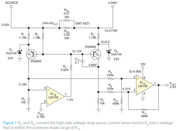
This design concept originated from the lack of access to advanced integrated circuits (ICs) that are capable of sensing current. A discrete circuit was required that could be easily constructed while still maintaining accuracy comparable to that of modern...
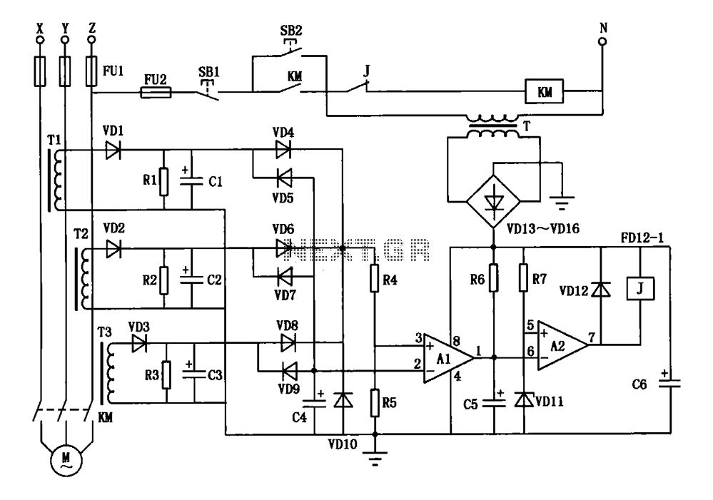
A current three-phase motor phase protection circuit is designed to detect three-phase current using homemade small current transformers T1, T2, and T3. The current signals are collected by rectifiers VD1, VD2, and VD3, while capacitors C1, C2, and C3...
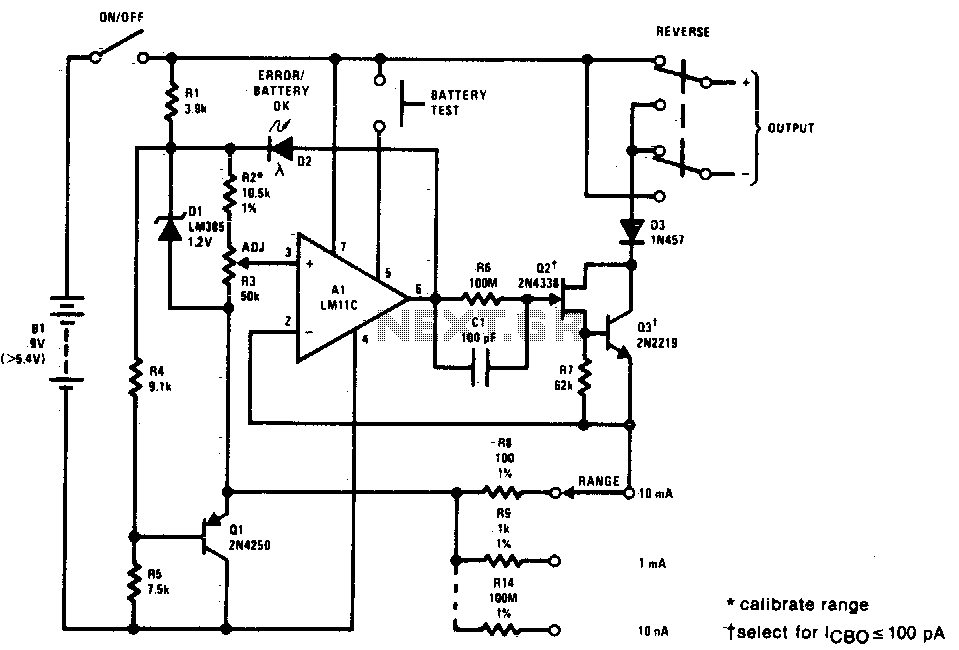
This precision current source features output current ranges from 10 µA to 10 mA, with an output compliance of 30 V to -5 V. The output current is fully adjustable within each range using a calibrated ten-turn potentiometer. An...
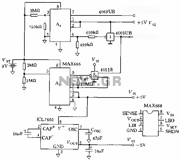
The microprocessor utilizes a linear regulator power circuit that is constructed using two MAX666 devices. The power supply for the CPU and A/D converter is connected to A2, while the RAM and real-time clock receive power from A1. The...
This regulator circuit stabilizes the output voltage at 200V directly (without a transformer). Although the output voltage is high, this circuit only suffers a. The circuit in question is designed to maintain a stable output voltage of 200V without the...