
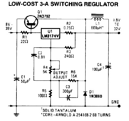
LM317 Low-Cost 3A Switching Regulator

The switching voltage regulator circuit operates by converting a higher input voltage to a lower output voltage with minimal energy loss, making it suitable for applications where efficiency is crucial. The core components typically include an inductor, a switch (usually a transistor), a diode, and output capacitors.
In the circuit, the switch alternates between the on and off states, controlling the energy transferred to the inductor. When the switch is closed, current flows through the inductor, storing energy in the form of a magnetic field. When the switch opens, the inductor releases its stored energy through the diode to the output load. This process allows for efficient voltage regulation and minimizes heat generation compared to linear regulators.
The output voltage can be adjusted using feedback mechanisms that monitor the output voltage and compare it to a reference voltage. This feedback loop ensures that the output voltage remains stable despite variations in load current or input voltage. Additional components such as capacitors at the input and output help filter voltage ripples, ensuring a smooth and stable output.
Overall, this switching voltage regulator circuit is ideal for applications requiring efficient power management, such as battery-operated devices, power supplies for microcontrollers, and other electronic systems where space and energy efficiency are paramount.A switching voltage regulator circuit shown in the schematic diagram here can be a low cost solution for your high efficiency requirement electronic circuit.. 🔗 External reference
Related Circuits
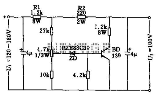
The circuit features no-load and short circuit protection mechanisms. To accommodate short circuit conditions, it is necessary to increase resistors R1 and R2 to allow for power dissipation; for example, R1 can be set to 1.2kΩ with a power...
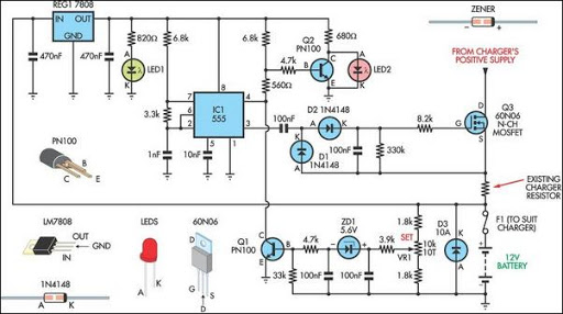
Most off-the-shelf car battery chargers cannot be left connected to the battery for long periods of time as overcharging can cause battery damage. The operation of car battery chargers typically involves converting alternating current (AC) from a wall outlet into...
The following diagram illustrates a 50W offline switching power supply circuit design. The circuit is powered by a MOSFET, specifically the BUZ80A/IXTP4N8 for a 220V AC voltage input and the GE IRF823 for a 110V AC input voltage. The...
40V regulated power supply based on TIP42A and LM317. Refer to the specified page for an explanation of the related circuit diagram. The 40V regulated power supply utilizes a TIP42A transistor and an LM317 voltage regulator to provide a stable...
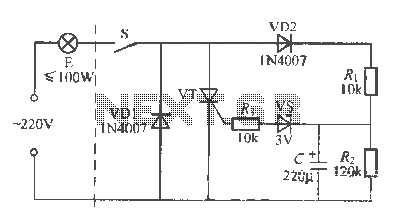
An incandescent lamp operates with a two-wire connection and features a life extension open circuit. It has a longer warm-up time compared to other types of lamps, resulting in a significant delay before illumination. Upon closing the switch, a...
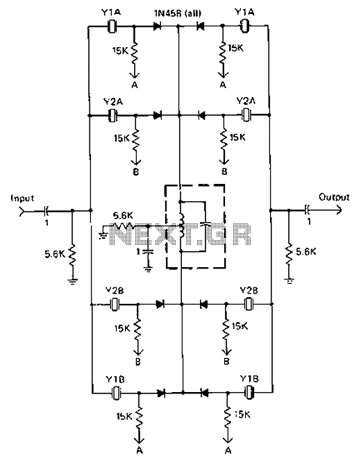
A 9-12V DC power supply is connected to control point A or point B for an amateur communication receiver IF amplifier, offering two distinct options. The power frequency is set at 455 kHz with a bandwidth of 500 Hz....