
LM317 Regulator Circuit

The LM317T voltage regulator is a versatile and widely used component in electronic circuits, capable of providing a stable output voltage with a maximum output current of 1 amp. It operates with an input voltage range typically up to 14 volts, making it suitable for various applications, including powering low-voltage devices.
In the described circuit, the LM317T is configured with appropriate resistors to set the desired output voltage. The output voltage can be adjusted by changing the resistor values connected to the adjustment pin of the LM317T. This allows for flexibility in powering devices that require different voltage levels. However, if the circuit is intended for devices that operate at a single voltage, the adjustable feature may be unnecessary.
To ensure reliable operation, a heatsink is mandatory for the LM317T, as it dissipates heat generated during voltage regulation, especially when the input voltage is significantly higher than the output voltage. The heatsink should be appropriately sized to maintain the regulator's temperature within safe limits during operation.
The circuit includes DC power jacks for both input and output connections, facilitating easy integration into various setups. The incorporation of a green power LED serves as a power indicator, illuminating when the circuit is powered on. Additionally, a red over-voltage LED is included to provide a visual alert if the output voltage exceeds a predetermined threshold. This LED is controlled by a zener diode, which is selected based on the specific voltage level required for activation; in this case, a 6.2V zener diode is utilized.
The zener diode's breakdown voltage can be adjusted by selecting a different zener, allowing for customization of the over-voltage protection feature. This is particularly beneficial for safeguarding sensitive electronic components from damage due to excessive voltage.
Overall, this voltage regulator circuit is designed for practicality and efficiency, providing essential features for voltage regulation while ensuring user safety through visual indicators and over-voltage protection.The voltage regulator is an LM317T, and should accept up to about 14 volts without problems. It can handle up to 1 amp, but you WILL need a heatsink on the voltage regulator. I also added DC power jacks for input and output on my voltage regulator, a green power LED, and a red over-voltage LED. The over voltage LED uses a zener diode to switch on the LED at a certain preset voltage, this can be varied depending on the voltage of the zener diode, I used a 6.2v zener diode.
If you plan to vary the voltage for the different items you power, don`t bother adding this feature. If you only plan to use items that run on one voltage, this is a very useful feature and will save plugging in and damaging your valuable (or not so 🔗 External reference
Related Circuits
The following circuit illustrates the use of a 555 integrated circuit (IC) for an infrared (IR) remote control extender circuit. Features include support for 850 nm and 950 nm signal wavelengths, along with the capability to generate control pulses. The...
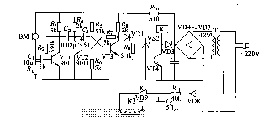
Cook in advance to open the door with a coal stove; before using the fire, it should be strong. This is an automatic door opening device that can automatically open the door before the regular homeowner, eliminating the need...
This project is designed to program the 8-pin PIC12c508A and 18-pin PIC16F84 microcontroller chips to support the projects we have designed; however, it will also program a number of other 8-pin and 18-pin microcontrollers, and the full list can...
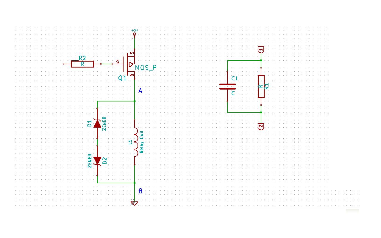
Although this may be a basic question, there is still some struggle with it. In this schematic, two zener diodes D1 and D2 are connected back-to-back across relay coil L1. The breakdown voltage (BVds) is -30V for Q1. The...
When the unit is positioned near a live conductor, whether insulated or buried in plaster, capacitive coupling occurs between the live conductor and the probe. This interaction activates the counter, resulting in the LED flashing five times per second,...
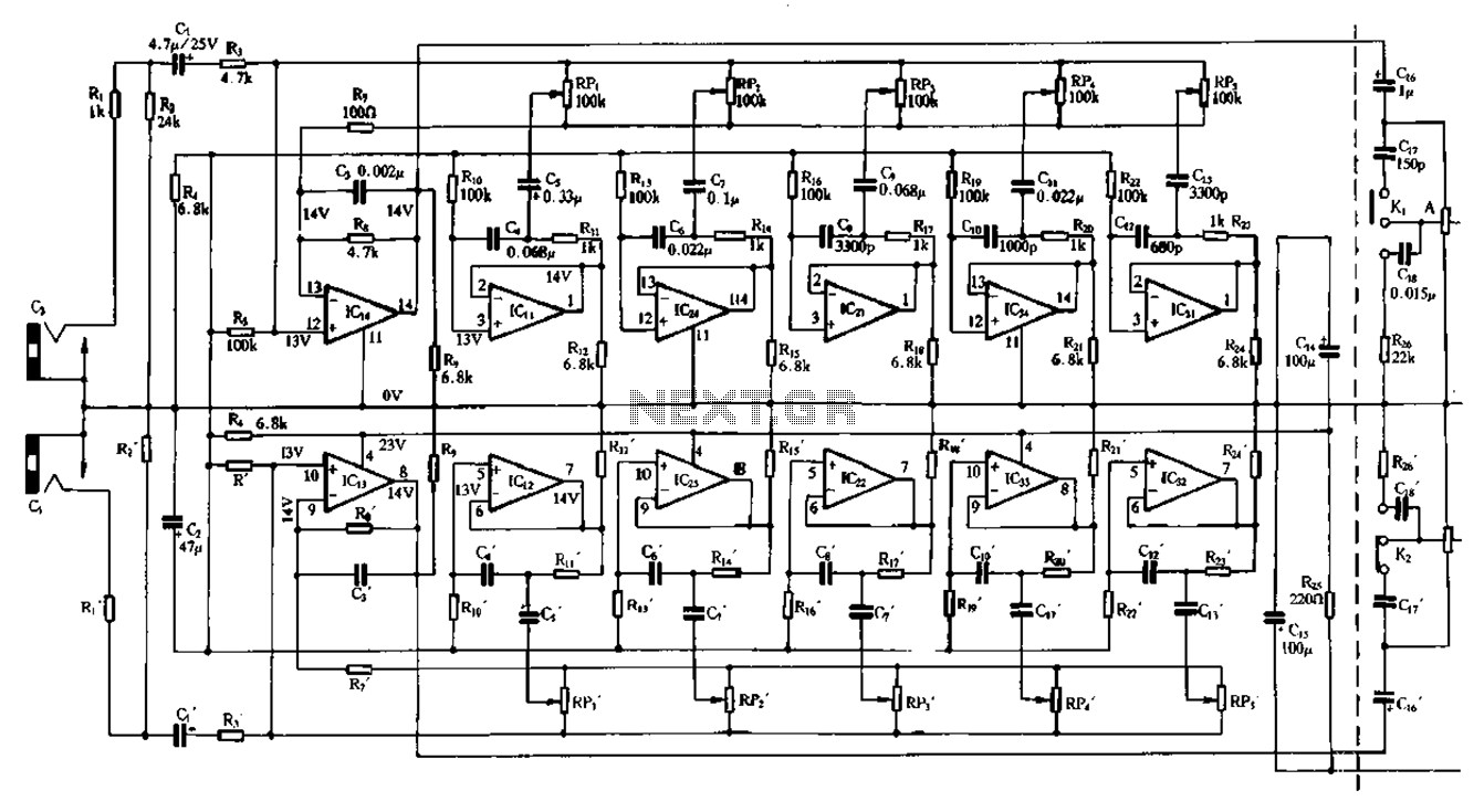
Figure 1-98 illustrates a double five-band equalizer circuit featuring a secondary connection. In this configuration, IC1 and IC14 serve as voltage amplifiers for each channel of the equalizer. The circuit also includes IC11, IC24, IC2, IC34, IC31, IC12, IC23,...