
LM35 IC Thermal Control

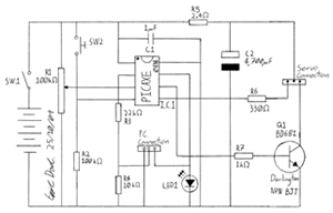
The LM35 IC thermal control circuit is designed to monitor temperature and provide a corresponding output voltage that is linearly proportional to the Celsius temperature. The LM35DZ sensor is a precision temperature sensor capable of measuring temperatures from -55°C to 150°C. The output voltage from the LM35DZ increases by 10 mV for each degree Celsius rise in temperature, allowing for straightforward interfacing with analog-to-digital converters (ADCs) or microcontrollers.
The circuit typically includes the LM35DZ connected to a power supply, often 5V, with the output pin connected to an ADC input for digital processing. A resistor divider network may be employed to set a reference voltage to compare against the LM35 output to determine when the temperature exceeds a specified threshold. This setup can trigger an alert, activate a cooling fan, or engage a heating element, depending on the application.
Additional components often integrated into the circuit include capacitors for noise filtering and stability, as well as operational amplifiers for signal conditioning if higher precision is required. The design may also feature hysteresis to prevent rapid on-off cycling around the threshold temperature, enhancing the reliability of the thermal control system.
This LM35 thermal control circuit is widely applicable in HVAC systems, automotive temperature monitoring, and various industrial processes where temperature regulation is critical. Proper layout and component selection are essential for ensuring accuracy and responsiveness of the temperature control system.Description: LM35 IC Thermal Control Circuit Diagram. Features: LM35DZ detect when the temperature is higher than the preset level, can be used in .. 🔗 External reference
Related Circuits
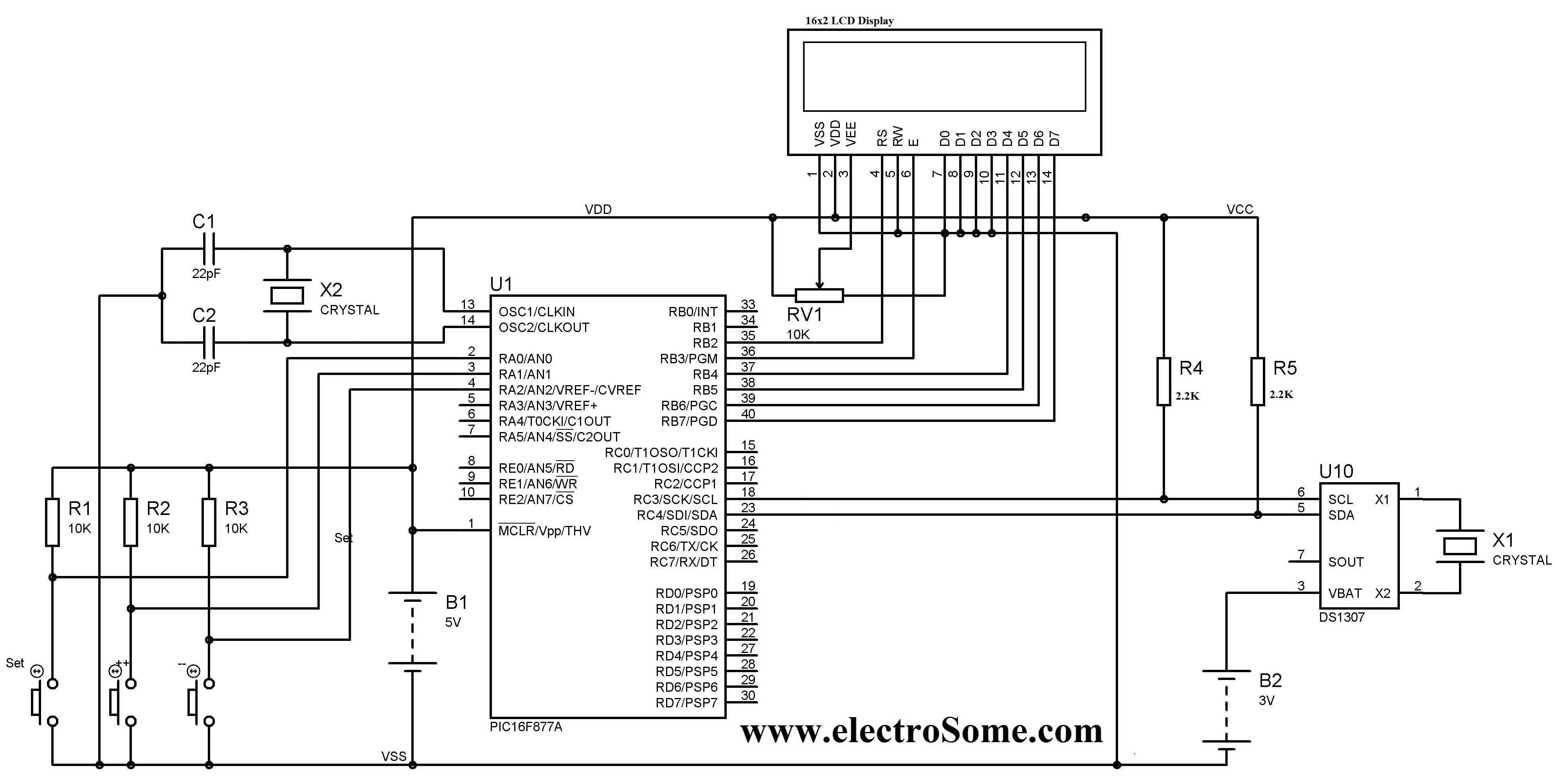
A digital clock can be constructed using a PIC microcontroller, DS1307 real-time clock (RTC), and a 16x2 LCD display. The DS1307 RTC operates in either 24-hour or 12-hour mode with an AM/PM indicator. It adjusts automatically for months with...
This circuit is constructed around a 555 timer and utilizes very few components. Due to its simplicity, even beginners can easily assemble and use it as a control device. A readily available laser pointer can be employed to operate...
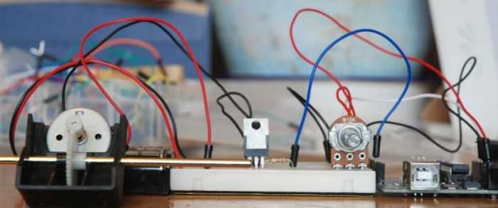
A quick circuit showing how to control the speed of a DC motor with a potentiometer with your Arduino board. Also shows how to use a TIP120 transistor to allow the Arduino control a larger power supply. This circuit utilizes...

The proposed remote control circuit can be utilized to control any electrical device within a range of 100 meters. This concept involves modifying an existing remote bell unit circuit, making the process straightforward. However, the construction aspect necessitates electronic...
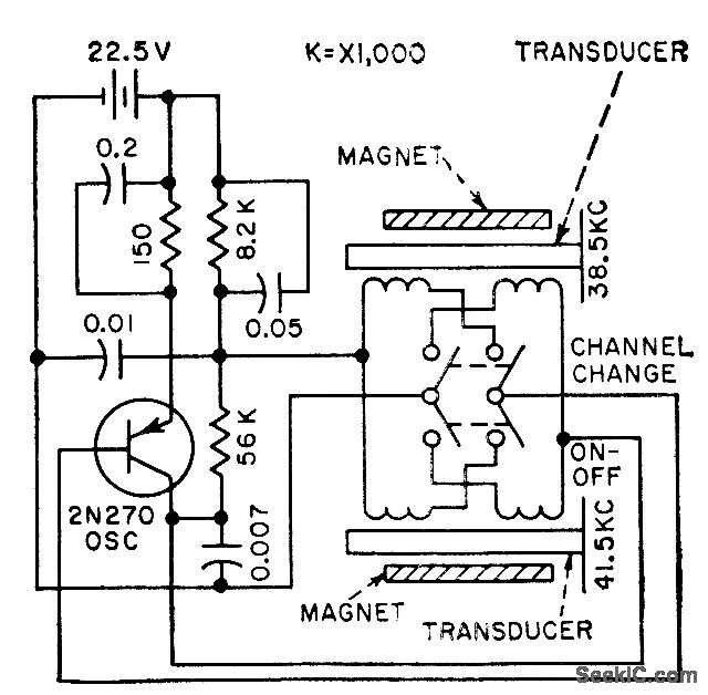
The frequency of a transistor oscillator is regulated by two different lengths of nickel tubing, each containing two coil windings. One coil functions as a driver, while the other serves as a pickup to generate feedback voltage necessary for...
This project involves creating a programmable camera controller using basic hand tools and a digital camera. By utilizing components that are commonly found at home, the overall costs can be minimized. A servomotor can be repurposed from a radio-controlled...