
LM350 Regulator 3-Amp Adjustable

This circuit likely employs a variable voltage regulator or a similar topology that allows for a wide range of output voltages. The design may include adjustable resistors or potentiometers to fine-tune the output voltage within the specified range.
In a typical configuration, the input voltage should be higher than the maximum output voltage to ensure proper regulation. This could be achieved using a power supply with an output voltage of at least 15 volts to accommodate the dropout voltage of the regulator.
The circuit may also incorporate bypass capacitors at the input and output to stabilize voltage levels and filter out noise. These capacitors should be chosen based on the frequency response requirements of the application.
In addition, the use of heat sinks may be necessary if the circuit is expected to handle higher currents, as voltage regulators can dissipate significant power when stepping down voltage. The thermal performance of the device should be considered during design to prevent overheating.
The output voltage can be monitored using a multimeter or oscilloscope to ensure it operates within the desired range. Proper layout and grounding techniques should be employed to minimize electromagnetic interference and ensure stable operation.
Overall, this circuit is versatile and can be utilized in various applications, including power supplies for sensors, microcontrollers, or other electronic devices requiring a stable voltage source.With the component values shown the circuit is designed to have and output voltage range of approximately 1.25 to 13.5 Volts when measured at the output of the.. 🔗 External reference
Related Circuits
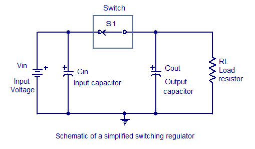
Switching regulators operate by drawing small amounts of energy from the input source and transferring it incrementally to the output. This is achieved using an electronic switch, which functions at a predetermined frequency, acting as a gate between the...
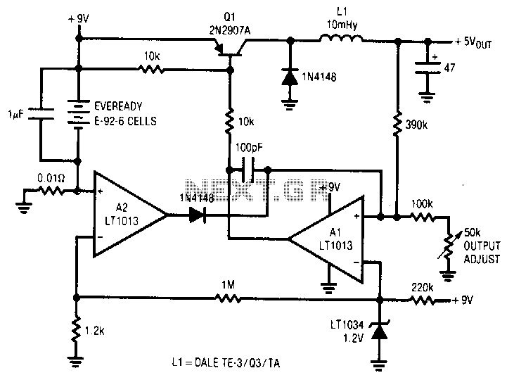
A simple battery-powered switching regulator provides 5 V output from a 9-V source with 80% efficiency and a 50 mA output capability. When Q1 is activated, its collector voltage increases, allowing current to flow through the inductor. This causes...
This regulator is suitable for devices that need up to 1mA. For higher output current, the resistors would have to be scaled down in reverse proportion to the peak current expected. With the resistor values shown, the regulator draws...
This device is designed to be a simple, inexpensive comparator intended for use in a solar cell power supply setup where a quick indication of "too low" or "just right" voltage is needed. The circuit consists of one 5V...
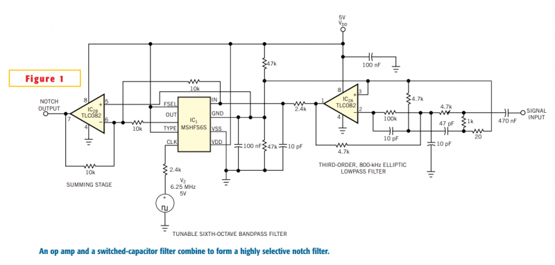
Although you can obtain universal, resistor-programmable switched-capacitor filters that are configurable as notch filters, most cannot operate at bandwidths higher than 100 kHz. Further, the typically 16- to 20-pin packages do not include a continuous-time, antialiasing filter to prevent...
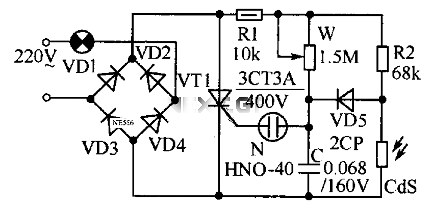
This circuit is designed to automatically adjust the brightness of lights based on the ambient light intensity. In bright conditions, the lights remain off, while in low ambient brightness, the lights are activated. The circuit incorporates a thyristor (VT1)...