
LME49810 IC For Power Amplifier

The LME49810 is a high-performance audio power amplifier IC designed to deliver high output power with low distortion. It is particularly well-suited for driving speakers with a nominal impedance of 4 ohms, making it ideal for various audio applications, including home theater systems and professional audio equipment.
The circuit typically consists of the LME49810 connected to a power supply, with additional components such as resistors and capacitors to stabilize the operation and enhance performance. The power supply voltage should be selected based on the desired output power and the specifications of the LME49810, which can operate efficiently within a range of supply voltages.
Key features of the LME49810 include its ability to provide high output current, which is essential for driving low-impedance loads without significant distortion. The circuit design often incorporates feedback mechanisms to ensure linearity and minimize harmonic distortion, which is critical in high-fidelity audio applications.
In the schematic, the input stage typically includes capacitive coupling to block DC components from the audio source, allowing only the AC audio signal to pass through. The output stage is usually connected to a suitable heatsink to dissipate heat generated during operation, ensuring reliable performance over extended periods.
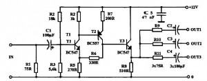
Overall, the LME49810 circuit is designed to deliver high-quality audio amplification, making it a popular choice among audio engineers and enthusiasts. Proper layout and component selection are crucial for achieving optimal performance and minimizing noise in the final audio output.The following circuit shows about LME49810 IC For Power Amplifier Circuit Diagram. Features: better drive 4 ? impedance of the speakers, for the .. 🔗 External reference
Related Circuits
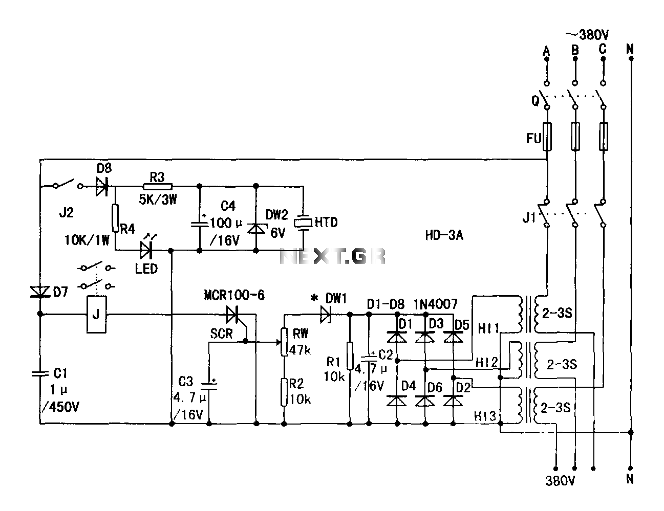
A current transformer H11-3 needs to be constructed. Select a transformer core with a minimum power rating of 2W for the first secondary winding. Use enameled wire with a diameter of 0.12 mm and wind approximately 1000 turns. The...
A 30W Class AB power amplifier circuit diagram utilizes a power transistor. To set up the amplifier, adjust the variable resistor R1 to its maximum value and R12 to zero. After completing this setup, activate the amplifier. Adjust R1...
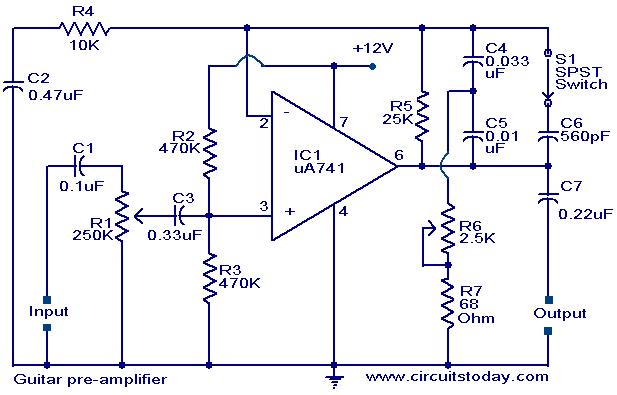
A preamplifier circuit designed for high-impedance electric guitar pickups is presented. This circuit utilizes a uA 741 operational amplifier (IC1) configured as a non-inverting amplifier. The potentiometer R1 functions as a volume control, while potentiometer R6 serves as a...
This circuit utilizes a 74HC14 hex Schmitt trigger inverter as a square wave oscillator to drive a small signal transistor configured in a class C amplifier setup. The frequency of the oscillator can be either fixed using a crystal...
A buffered video amplifier is utilized to connect a video player to a receiver or monitor TV over long cable lengths, which may lead to a reduction in signal amplitude and, consequently, a decline in image quality. This amplifier...
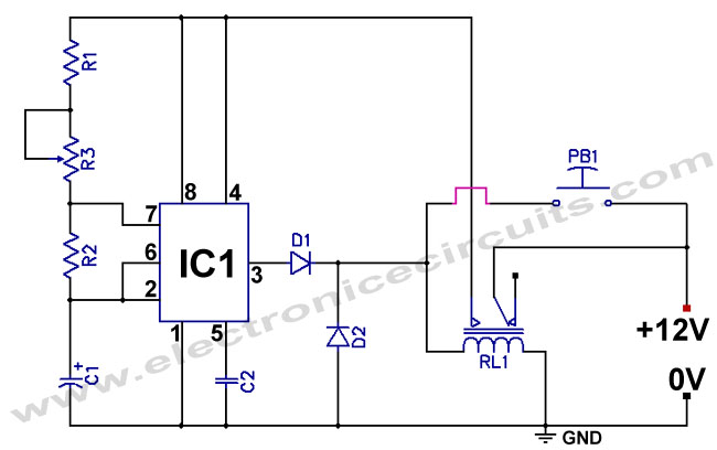
The standard 555 timer circuit consumes power from the battery even when the start push-button (PB1) is not pressed, due to a potential divider created by three 5kΩ resistors within the integrated circuit (IC). This power consumption, referred to...