
Logic probe

The circuit utilizes the LM393 dual voltage comparator to monitor the input voltage levels in relation to the defined thresholds of 70% and 30% of the supply voltage. The LM393 is a versatile device that can operate with supply voltages ranging from 2 V to 36 V, making it suitable for applications requiring a wide voltage range. In this configuration, the comparator outputs are used to determine whether the input voltage is above or below the specified thresholds.
When the input voltage exceeds 70% of the supply voltage, the first output of the LM393 transitions to a high state, illuminating an LED to indicate this condition. Conversely, when the input voltage falls below 30% of the supply voltage, the second output of the LM393 goes high, activating another LED to signify the low state.
The output signals from the LM393 are used to trigger a CMOS oneshot timer, specifically the MC14538. This timer is configured to respond to the rising edge of the LM393 outputs. The use of 1N4148 diodes ensures that the output signals are properly isolated and that only the rising edge triggers the oneshot. The MC14538 can generate a single pulse of a predetermined duration, which is useful for applications requiring a brief output signal in response to the detected voltage levels.
The RC values associated with the MC14538 determine the pulse width and timing characteristics of the output pulse. By selecting appropriate resistor and capacitor values, the circuit can reliably trigger at frequencies greater than 30 kHz for both sine and square wave inputs, ensuring robust performance across a range of signal types. This capability makes the circuit suitable for various applications, including voltage monitoring, signal conditioning, and indicator systems.The probe indicates a high or low at 70% and 30% of V+ (5 to 12 V). One section of the voltage comparator (LM393) senses V in over 70% of supply and the second section senses V in under 30%. These two sections direct-drive the appropriate LEDs. The pulse detector is a CMOS oneshot (MC14538) triggered on the rising edge of the LM393 outputs through 1N4148 diodes
With the RC values shown, it triggered reliably at greater than 30 kHz on both sine and square waves.
Related Circuits
This circuit is a Logic Probe. It indicates the logic state of the node of any TTL logic circuit. To do that, we have to supply the probe with the same power of the circuit that we want to...
This is a simple circuit of a Logic Probe for tri-state logic. This circuit can be built in just a few hours. Additionally, this circuit has other features. The Logic Probe circuit for tri-state logic is designed to detect and...
This probe is useful for any low level RF work, and simply connects to your multimeter. The voltage shown will not be accurate, since this is a rectifier probe, but the measurements are good enough for you to be...

A logic probe is a circuit that indicates the logic state of a node in any TTL logic circuit. It operates when supplied with the same power level. A logic probe is an essential diagnostic tool used in digital electronics...
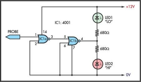
This simple logic probe has both LEDs illuminated with no signal at the input. However, due to the NOR gates connected to the probe, it indicates correctly when a high or low signal is present. It also functions correctly...
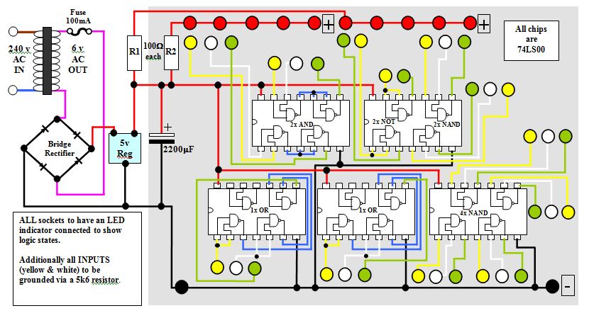
This circuit diagram for a logic tutor kit was created using MS Word graphics. While modern software is commonly utilized, there may be instances where traditional methods are necessary. Employ a sharp pencil and a ruler to ensure precision;...