
The sound of a photoelectric conversion circuit

The circuit design comprises several key components that work together to facilitate the conversion process. The audio input from a source, such as a radio or music player, is fed into the circuit through a dedicated input socket. The initial stage involves the transistor (VT), which acts as an amplifier to boost the audio signal sufficiently to drive the LED. The LED is crucial in this setup, as it converts the electrical audio signal into light, which is then transmitted via the fiber optic cables.
The role of the resistor (Ri) is essential for ensuring that the circuit maintains proper impedance matching. This matching is critical for maximizing power transfer and minimizing signal loss, which is particularly important in audio applications where fidelity is paramount.
Once the light signal travels through the fiber optic connectors, it reaches the photodiode (Ran, VLS). The photodiode functions as a light sensor, converting the incoming light back into an electrical signal. This signal is generally weak and requires further amplification. The pre-amplifier stage, which includes another transistor (VT), boosts the signal strength before it is sent to the LM386 power amplifier.
The LM386 is a low-voltage audio power amplifier that is well-suited for driving small speakers. It is designed to deliver sufficient power to reproduce sound effectively without requiring excessive voltage levels. The output from the LM386 is connected to the speaker (BL), which converts the amplified electrical signal back into audible sound waves.
To enable user control over the output volume, the circuit incorporates a potentiometer (RP). This adjustable resistor allows the user to set the desired sound level, providing flexibility and enhancing the usability of the system.
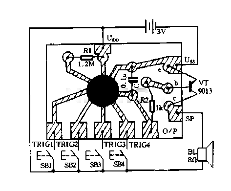
Overall, this circuit exemplifies a straightforward yet effective approach to converting audio signals into light and back into sound, utilizing basic electronic components to achieve the desired functionality in an experimental setup. Circuit works as follows: The electrical circuit is a light, a light electric sound conversion circuit with two simple fiber optic connector for experimental play is shown. f W hat the electrical diagram showing a conversion circuit. Audio radio, music and other audio Xin headphone jack output from the input socket xs, after VT amplified by the drive LED light signals emitted by audio signals modulated complete electro-optical conversion. Circuit Ri is the role of the circuit input impedance of the radio, Walkman and other audio output impedance matching.
Figure showing b} sound power conversion circuit. LED light signal emitted after the optical fiber transmission received by the photodiode f Ran, VLS converting the received optical signal into an electrical signal weak. This pre-amplifier via the transistor VT and other electrical components of the composition of an enlarged and then sent people LM386 IC power amplifier, speaker BL push restore the sound to achieve a light electric sound conversion.
Circuit RP is the volume adjustment potentiometer.
Related Circuits
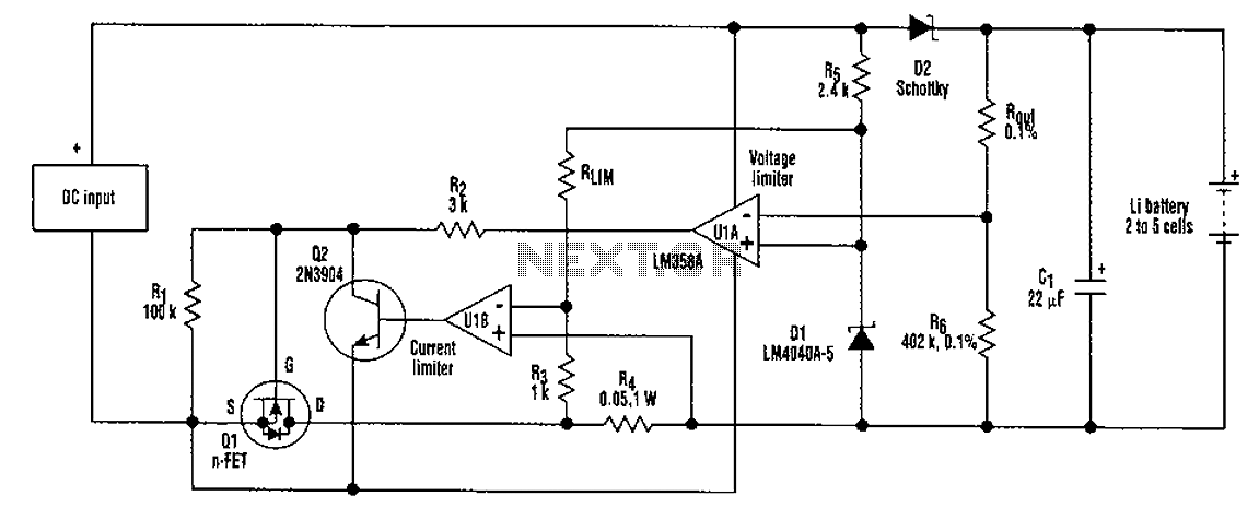
A universal rechargeable lithium battery circuit design, applicable to different battery types and numbers of batteries. This is because both the charger output voltage or current limit setpoint and the maximum charging current can be adjusted by simply changing...
This is a power-on time delay relay circuit that utilizes the emitter/base breakdown voltage of a standard bipolar transistor. The reverse-connected emitter/base junction of a 2N3904 transistor functions as an 8-volt zener diode, establishing a higher turn-on voltage for...
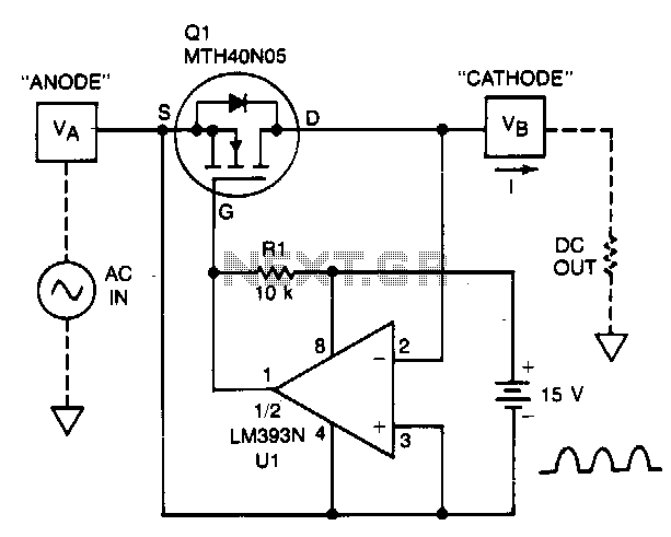
A TMOS power FET, Q1, and an LM393 comparator provide a high-efficiency rectifier circuit. When voltage V1 exceeds V2, the output of U1 becomes high, and Q1 conducts. Conversely, when V2 exceeds V1, the comparator output becomes low, and...
A simple thermostat circuit that can control a relay to supply power to a small space heater through the relay contacts. The relay contacts must be rated above the current requirements for the heater. Temperature changes are detected by...
Constantly changing light and sound analog controller circuit 07 The circuit described is an analog controller designed to modulate light and sound in a dynamic manner. This circuit utilizes various electronic components to create an interactive experience where both light...
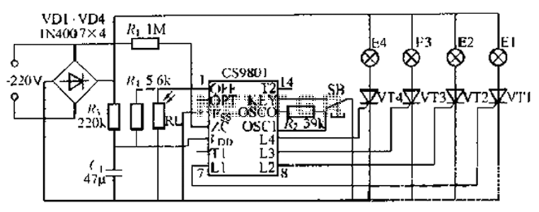
The ASIC is a flashing light string controller featuring four outputs. It includes a single key cycle control with six different lighting effects, and it allows for the selection of either 16 or 8 patterns. The circuit incorporates a...