
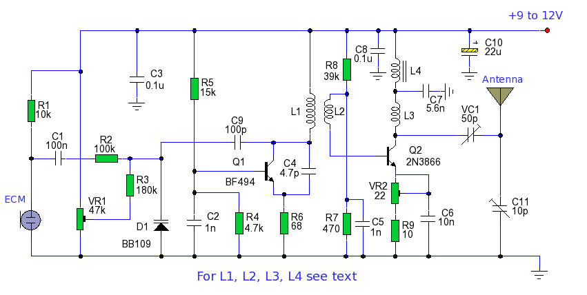
Long Range FM Transmitter

The FM transmitter circuit operates within the designated frequency band, ensuring compliance with FM broadcasting standards. The core of the circuit typically includes a voltage-controlled oscillator (VCO) that generates the desired frequency. The stability of the transmitter is enhanced by using high-quality components, such as low-noise transistors and precise capacitors, which minimize frequency drift.
To achieve harmonic suppression, the circuit may implement a band-pass filter that allows only the desired frequency to pass while attenuating unwanted harmonics. This feature is crucial for maintaining signal clarity and preventing interference with adjacent channels. The transmitter's output stage is designed to provide sufficient power to achieve the specified range of 5 km, often utilizing a class C amplifier for efficient operation.
Power supply considerations are also essential, as the circuit must maintain stable voltage levels to ensure consistent performance. Bypass capacitors are typically used to filter out noise from the power supply, further contributing to the overall stability of the transmitter.
A tuning mechanism, often in the form of a variable capacitor or an adjustable inductor, allows for fine-tuning of the output frequency, enabling the user to select any frequency within the 88 to 108 MHz range. Additionally, an antenna matching network may be included to optimize the impedance between the transmitter and the antenna, maximizing the effective radiated power.
Overall, this FM transmitter circuit is suitable for various applications, including hobbyist projects, educational purposes, and small-scale broadcasting, where a reliable and stable transmission is required.This is very stable, harmonic free, long range fm transmitter circuit which can be used for fm frequencies between 88 and 108 MHz. This can cover 5km range.. 🔗 External reference
Related Circuits
This set of two circuits forms the basis for a simple light wave transmitter. A laser beam is modulated and directed toward a receiver that demodulates the signal, subsequently presenting the information (voice, data, etc.). The assembly is straightforward and...
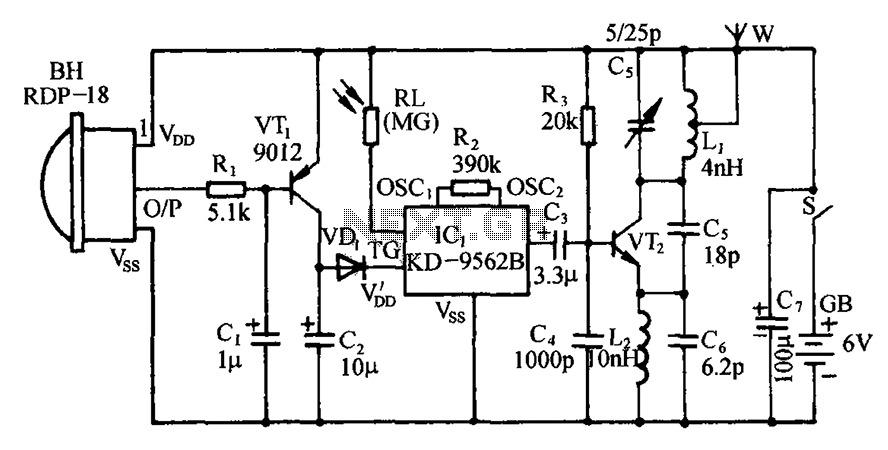
The circuit includes an infrared sensor head, electronic switches, an audible audio circuit, and an FM radio circuit. It is designed for installation in banks, treasuries, and other areas requiring supervision during evening hours in lieu of staff presence....
The power output of many transmitter circuits is low due to the absence of power amplifier stages. The transmitter circuit presented here includes an additional RF power amplifier stage after the oscillator stage, which elevates the power output to...

Electronic FM Telephone Transmitter Schematic. The following schematic design illustrates a circuit diagram for an FM telephone transmitter built on a compact PC board layout. This small design allows it to be easily integrated within the housing of a...
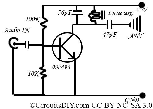
This is a simple and inexpensive FM transmitter. The circuit operates at a low voltage using a CR2025 3V battery with low current consumption. The total size of this FM transmitter, including the battery but excluding the antenna, is...

This circuit represents an FM transmitter, also referred to as an FM Bug, which consists of 18 essential components for optimal functionality. The circuit begins with an electret microphone on the far left side, and the signal flows electrically...