
Low-Cost and Simple Intercom

The intercom circuit is designed to facilitate two-way audio communication between two locations. The core of the circuit comprises three transistors, which serve various functions such as amplification and signal switching.
Transistor Q1 acts as a microphone amplifier, receiving audio signals from the microphone and boosting them to a suitable level for further processing. This transistor is typically configured in a common-emitter configuration, which provides a significant voltage gain. The microphone should be a low-impedance type to ensure optimal performance.
Transistor Q2 functions as a driver stage, taking the amplified signal from Q1 and further increasing its power to drive the speaker. This transistor is also configured in a common-emitter arrangement, allowing it to deliver sufficient current to the speaker without distortion. It is important to choose a speaker with an appropriate impedance that matches the output of Q2 to maximize efficiency.
Transistor Q3 is used for signal switching, enabling the user to toggle between the two communication ends of the intercom system. This can be accomplished using a simple push-button switch connected to the base of Q3, which controls its on/off state. When engaged, Q3 allows the audio signal from the microphone to be routed to the speaker, facilitating communication.
Power supply requirements for the circuit are minimal, typically operating at low voltage levels, which makes it suitable for battery operation or connection to a low-voltage power source. Decoupling capacitors should be included in the design to filter out any noise from the power supply, ensuring clear audio transmission.
Overall, this intercom circuit design is not only cost-effective but also straightforward to assemble, making it an ideal project for beginners in electronics. The use of transistors allows for reliable performance while keeping the component count low, promoting ease of understanding and implementation.This is a low-cost and simple intercom circuit design which utilizes 3 transistors. Even a newbie can assemble it on a piece of veroboard without difficulty 🔗 External reference
Related Circuits
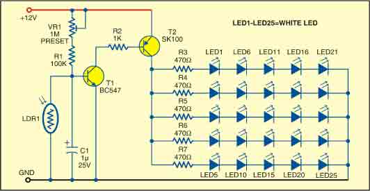
This sunlight-controlled lamp utilizes a light-dependent resistor (LDR) as the sunlight sensor and comprises a total of 25 high-brightness white LEDs. Each row of LEDs is connected in series with separate resistors. The operation of the circuit is straightforward....
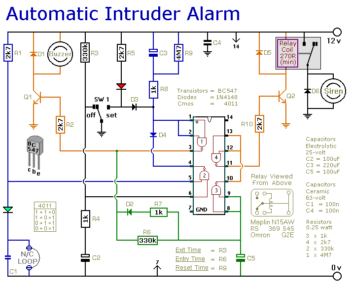
This is a simple single-zone burglar alarm circuit. Its features include automatic exit and entry delays and a timed bell/siren cut-off. It is designed to be used with the usual types of normally-closed input devices such as magnetic reed...
Schematic and description of a simple microphone amplifier circuit. This circuit contains two stages: the first is a microphone preamplifier, and the second is an audio amplifier using the LM386 Amplifier IC. The simple microphone amplifier circuit is designed to...
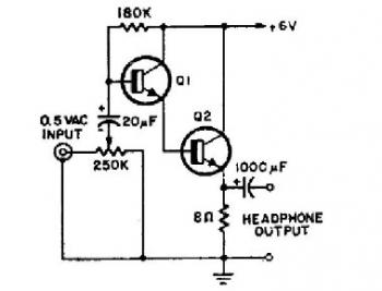
This schematic diagram illustrates a simple headphone amplifier circuit constructed using two NPN transistors. Suitable transistor options include the BC549C, as well as other NPN transistors such as the European equivalents BC548C, BC547C, BC239, 2N5818, or 2N2222. An audio...
The two circuits di atas illustrate opening a relay contact a short time after the ignition or light switch is turned off. The capacitor is charged and the relay is closed when the voltage at the diode anode rises...
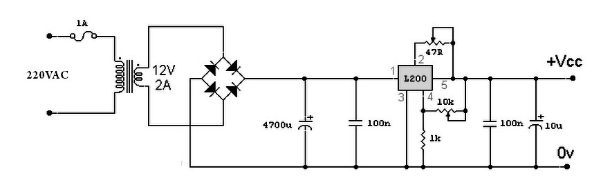
A variable power supply based on the L200 IC, where the output voltage is controlled by a 10K variable resistor. The output voltage ranges from approximately 3 to 15 volts, with a current output ranging from a minimum of...