
Musical Instrument Digital Interface (Midi) Transmitter Circuit
 Transmitter")
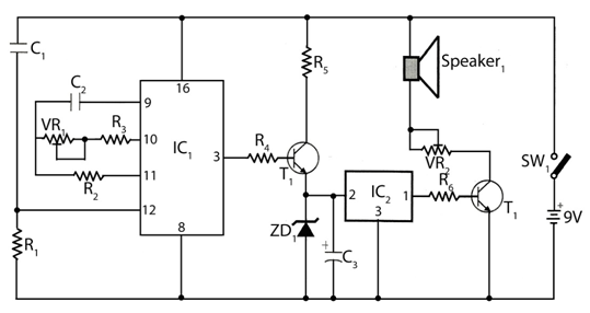
This circuit is designed to facilitate the digital control of musical instruments through the conversion of digital signals into optical signals suitable for transmission via fiber optic cables. The use of an optocoupler (IC1) is essential for ensuring electrical isolation between the digital control circuitry and the optical transmission components. This isolation protects sensitive components from potential voltage spikes and noise that could be present in the control signals.
The optocoupler IC1 interfaces with two additional integrated circuits, IC2-a and IC2-b, which may serve various roles such as signal processing, amplification, or additional isolation. The outputs from these ICs are then directed to T1, which is likely a transformer or a similar component that helps in further conditioning the signal before it reaches the optical transmission stage.
The final stage of the circuit involves a cable driver LED, specifically the SFH750 model. This LED is designed to emit light when driven by the processed signals from T1, effectively converting the electrical signals into optical signals. The SFH750 is chosen for its efficiency and compatibility with fiber optic transmission, ensuring that the signals maintain integrity over long distances.
Overall, this circuit is a crucial component in modern digital musical instruments, providing reliable communication through optical means while maintaining isolation and signal integrity throughout the process. Used for digital control of musical instruments, this transmitter converts the digital data signals to equivalent optical signals for fiberoptic cable interface. Optocoupler IC1 provides isolation, and drives IC2-a and -b and Tl, and finally provides a cable driver LED (SFH750).
Related Circuits

The circuit demonstrates a method for powering CMOS integrated circuits (ICs) using RS-232C lines. The MAX680 is typically employed to generate a voltage equal to ±2 Vcc. This circuit operates in the opposite manner, accepting ±10.5 to ±12V from...

The following circuit illustrates a Slave Flash Light Control Circuit Diagram. Features include a 68 mH inductor, which provides an automatic trigger for the secondary flash light. The Slave Flash Light Control Circuit is designed to enhance the functionality of...
The circuit timer with a musical alarm utilizes a well-known CMOS oscillator/divider integrated circuit (IC1). Although this circuit operates at 9V, its standby current drain is minimal. The time delay of the timer circuit can be adjusted by modifying...
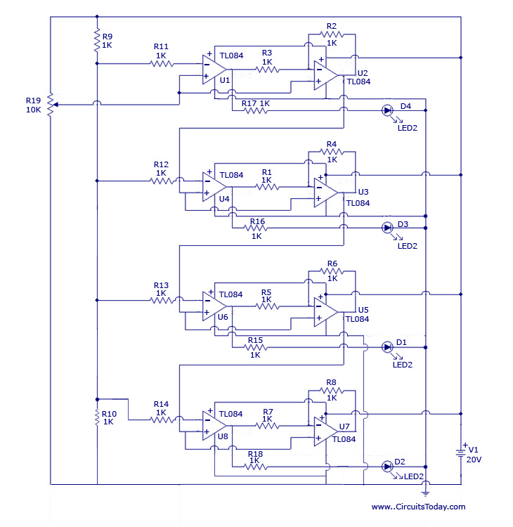
The design originated from the interest in discovering a new technique for analog to digital conversion. The two types of ADC (Analog to Digital Converter) that influenced the development of this circuit are the Flash Type ADC and the...
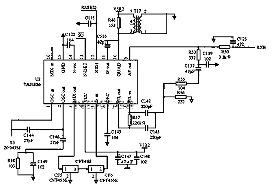
As illustrated in the figure, Vcc is the power supply for the circuit. Upon receiving the initial signal, the frequency is adjusted to 21.7 MHz. This frequency is subsequently enhanced through two crystal filters to improve the selectivity of...
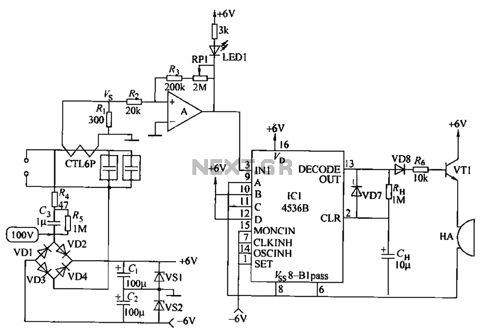
The circuit principle involves using a current transformer for current sensing due to the large AC power load of computers. This setup detects whether there is current in the power line, enabling the determination of its status. The LM393...