
Low cost light dimmer using an SBS and triac

The described light dimmer circuit employs a silicon-controlled rectifier (SCR) in conjunction with a triac to control the brightness of incandescent lamps. The primary function of the triac is to regulate the power delivered to the load by controlling the phase angle of the AC supply voltage.
In this circuit, the SCR is shunted by two 20K ohm resistors. This configuration serves to mitigate the flash-on effect, which is a common issue in light dimming applications where the load may briefly illuminate at full brightness when the circuit is activated. The use of two resistors in parallel effectively reduces the overall resistance seen by the SCR, allowing it to trigger more reliably and preventing the sudden surge of current that causes the flash-on effect.
The operation of the dimmer relies on the principles of phase control. By adjusting the trigger point of the triac, the circuit can vary the amount of time the load is energized during each half-cycle of the AC waveform. This is typically achieved using a variable resistor or potentiometer that alters the gate trigger signal to the triac.
The circuit can be designed to include additional components such as capacitors and diodes for further stabilization and to protect against voltage spikes, which can be detrimental to the SCR and triac. Proper heat sinking for the SCR and triac is also essential to ensure reliable operation, as these components can generate significant heat under load conditions.
Overall, this low-cost light dimmer circuit is suitable for various lighting applications, offering a practical solution for adjusting light levels while minimizing unwanted effects associated with traditional dimming methods.Low-cost light dimmer using an SBS and triac. Shunting the SBS with two 20K resistors minimizes the flash-on effect, courtesy Motorola Semiconductor Products Inc. 🔗 External reference
Related Circuits
What's so special about this circuit? Well, the first third-brake light I installed I had to pull a wire from the Third Brake Light all the way underneath the carpet to the brake-pedal-switch and I thought it would be...
Sun tracking systems significantly enhance the efficiency of photovoltaic (PV) arrays and are crucial for concentrated PV systems. This document discusses a light tracking servo model designed to simulate the movement of a PV array. A mathematical model is...
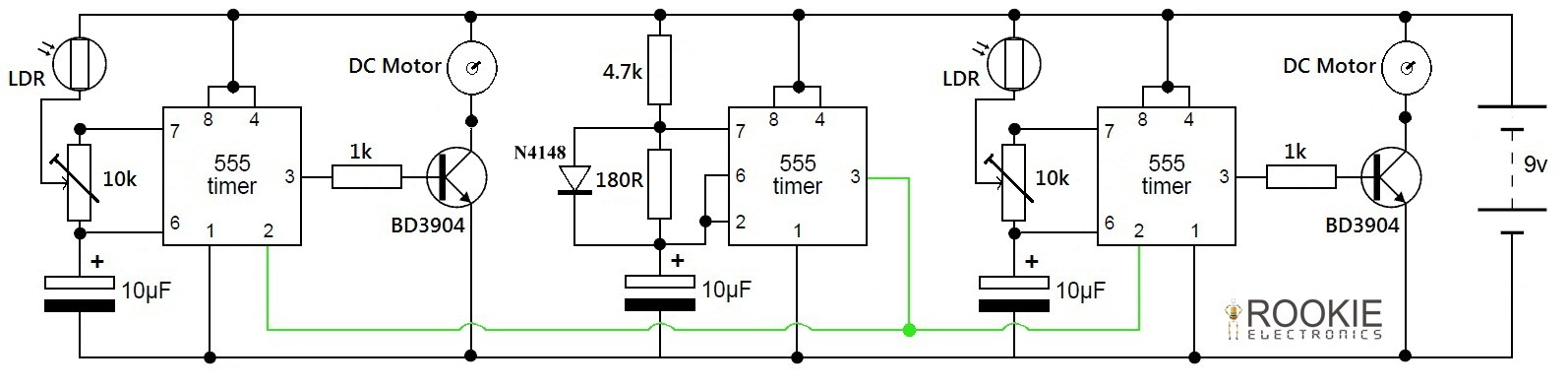
This is a simple and cost-effective approach to a line-following robot. It does not utilize any microcontroller but instead relies on a basic circuit composed of three 555 timers. The robot demonstrates good efficiency in following various curves and...
The output of this circuit is push-pull and consumes less than 3 mA (with no signal) but drives the earpiece to a very loud level when audio is detected. This circuit operates in a push-pull configuration, which allows it to...

The circuit diagram of an FM transmitter utilizes the IC UPC1651, which is a wideband UHF Silicon MMIC amplifier. This integrated circuit features a broad frequency response of up to 1200 MHz and a power gain of up to...

The circuit comprises three main components. The first component features an oscillator, while the second component includes a mod 16 counter (7493). The oscillator is configured in self-triggered mode, and a potentiometer (VR1) is utilized for speed control of...