
FM transmitter using UPC1651
The FM transmitter circuit based on the UPC1651 IC is designed for efficient signal amplification and modulation. The UPC1651 is specifically chosen for its high-frequency capabilities and gain characteristics, making it suitable for FM transmission applications. The circuit's power supply requirement of 5V DC ensures compatibility with a variety of power sources, allowing for versatile deployment in different environments.
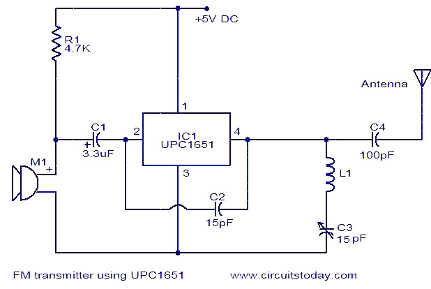
In the circuit, the microphone acts as the audio input source, capturing sound waves and converting them into electrical signals. These signals are then filtered through capacitor C1, which eliminates unwanted noise, ensuring that only the desired audio frequencies are sent to the IC. The IC amplifies these signals, preparing them for modulation.
The output from pin 4 of the UPC1651 is the modulated FM signal, ready for transmission. The LC circuit composed of inductor L1 and capacitor C3 plays a critical role in determining the frequency of the transmitted signal. By adjusting capacitor C3, the resonant frequency of the LC circuit can be varied, thus allowing for fine-tuning of the transmitter to specific frequency bands as required by the application.
This circuit can be applied in various scenarios, such as low-power broadcasting or personal audio transmission, where compactness and efficiency are essential. Proper design considerations, including the selection of components and layout, are vital to ensure optimal performance and minimize interference, thereby achieving a clear and stable FM transmission.Here is the circuit diagram of an FM transmitter using the IC UPC1651. UPC1651 is a wide band UHF Silicon MMIC amplifier. The IC has a broad frequency response to 1200MHz and power gain up to 19dB. The IC can be operated from 5V DC. The audio signals picked by the microphone are fed to the input pin (pin2) of the IC via capacitor C1. C1 acts as a n oise filter. The modulated FM signal will be available at the output pin (pin4) of the IC. Inductor L1 and capacitor C3 forms the necessary LC circuit for creating the oscillations. Frequency of the transmitter can be varied by adjusting the capacitor C3. 🔗 External reference
Related Circuits
The most important part of this 88-108 transmitter is the Colpitts oscillator. Capacitors C3, C4, C5, C6, diodes CD1 and CD2, and inductor L1 determine the transmission frequency. The RF oscillator... The Colpitts oscillator is a type of electronic oscillator...

The intention is to utilize this code in future projects involving 7-segment displays. For those interested in learning more about 7-segment displays, additional information can be found in a related post. 7-segment displays are widely used in electronic devices for...
This is a battery charger circuit that has the advantage of automatically disconnecting the battery when charging is complete. The voltage sensor used in this circuit is the LM301 IC, which serves to disconnect the battery when the charging...
A 40kHz ultrasonic transmitter circuit consists of three oscillators (F1, F2, and F3), with F3 generating a 40kHz square wave output. The frequency is primarily determined by components C1, R1, and an adjustable resistor (RP). The excitation output from...
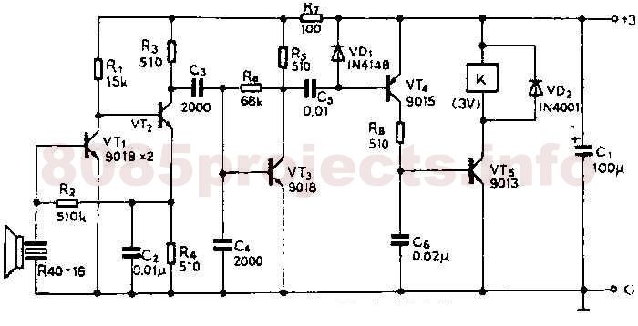
If the audio input is a microphone, it is expected to precede an amplifier to achieve an output power of approximately 8W. The amateur seeking to enhance a small transmitter, which is likely already constructed, can utilize this circuit,...
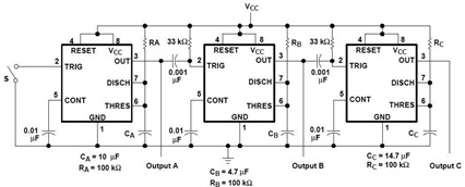
A sequential timer circuit device is utilized in various applications for initializing conditions during start-up or for activating test signals in sequences, such as in test equipment devices. The circuit diagram below illustrates a sequencer circuit with potential applications...
Warning: include(partials/cookie-banner.php): Failed to open stream: Permission denied in /var/www/html/nextgr/view-circuit.php on line 713
Warning: include(): Failed opening 'partials/cookie-banner.php' for inclusion (include_path='.:/usr/share/php') in /var/www/html/nextgr/view-circuit.php on line 713