
TDA2822 Audio Amplifier

The synthesizer kit utilizes an SPI DAC to convert digital signals into analog audio signals, which are then amplified by the TDA2822M audio amplifier. The TDA2822M is configured in a bridge mode to maximize power output, allowing for greater audio performance. This configuration effectively drives the speaker with higher efficiency, making it suitable for various audio applications.
The schematic for the TDA2822M includes connections for power supply, ground, input from the DAC, and output to the speaker. The gain of the amplifier must be carefully calculated to ensure that the output signal does not exceed the maximum voltage ratings, thereby preventing clipping and distortion. The gain setting can be adjusted based on the desired output levels, and it is essential to refer to the datasheet for precise values and configurations.
The microcontroller, likely an Arduino, serves as the central control unit for the synthesizer. The digital output from the Arduino is connected to the amplifier's input, enabling control over the audio signals. The tone function in the Arduino code generates specific frequencies that are sent to the amplifier, allowing for sound experimentation. The choice of using protoboard for assembly provides a robust platform for the components, ensuring reliability and ease of modifications during the development process.
In summary, this synthesizer kit represents an innovative approach to audio experimentation, combining a microcontroller, DAC, and audio amplifier in a compact and efficient design. The careful selection of components and configuration will facilitate a wide range of audio applications while maintaining cost-effectiveness.Usually the project is a variation on the POV toy, which you see around online all of the time as a beginner electronics project. However, we decided to deviate from our traditional path this year and create our own synthesizer kit, with an SPI DAC, Audio Amplifier, Microcontroller and some buttons.
There is also a possibility for programming in new wave forms via an optical link with a computer. To give a good overview of the whole project I plan on doing a write up on each part of the project as I go along. First up lets check the constraints of our Audio Amplifier and see if we can get it working in an appropriate way.
The amplifier we are using is a TDA2822M and is a dual audio amplifier. We are not driving a stereo channel, so we will be using the TDA2822M in a bridge configuration inorder to both push and pull on the speaker dramatically increasing the amount of power we can drive through the speaker. The datasheet for the TDA2822M is where the schematic above was pulled from. The schematic is a basic bridge, which drives both sides of the speaker in mono for added power. It is important to note the gain of the circuit for future calculations since the output of or DAC will be full swing from 0V to 5V (or close).
Thus we will need to divide those voltages so that we don`t clip everything to a funky looking square wave. At 1kHz the noted voltage gain is 39db, which is about Vin*89. 125. A rather respectable gain, which we will later have to contend with. I decided used to prototyping with breadboards, but this time I have decided to use protoboard and solder and skip breadboards completely.
While breadboards are nice I find that if I spend the time to sit down fully plan what I am doing and soldering it down on to protoboard that I reach an end result faster. Once the soldering was done (see schematic above), I hooked up the input of the TDA2822 Audio Amplifier to a digital output of an arduino and used the tone function.
The code that was used was straight from the Arduino examples. I just wanted to test that I could amplify sound and play it through the speaker. Both of the speakers I had available performed very well. However, the cost difference means that we should choose the lower cost speaker even though the sound quality is worse (but not by much). We want to minimise cost, while still providing a system which can be used to experiment with sound, or any application which requires a decent quality DAC.
/* Melody Plays a melody circuit: * 8-ohm speaker on digital pin 8 created 21 Jan 2010 modified 14 Oct 2010 by Tom Igoe This example code is in the public domain. */ #include "pitches. h" // notes in the melody: int melody[] = { NOTE_C4, NOTE_G3, NOTE_G3, NOTE_A3, NOTE_G3, 0, NOTE_B3, NOTE_C4}; // note durations: 4 = quarter note, 8 = eighth note, etc.
: int noteDurations[] = { 4, 8, 8, 4, 4, 4, 4, 4 }; void setup() { // iterate over the notes of the melody: for (int thisNote = 0; thisNote < 8; thisNote+) { // to calculate the note duration, take one second // divided by the note type. //e. g. quarter note = 1000 / 4, eighth note = 1000/8, etc. int noteDuration = 1000/noteDurations[thisNote]; tone(8, melody[thisNote], noteDuration); // to distinguish the notes, set a minimum time between them.
// the note`s duration + 30% seems to work well: int pauseBetweenNotes = noteDuration * 1. 30; delay(pauseBetweenNotes); // stop the tone playing: noTone(8); } } void loop() { // no need to repeat the melody. } 🔗 External reference
Related Circuits
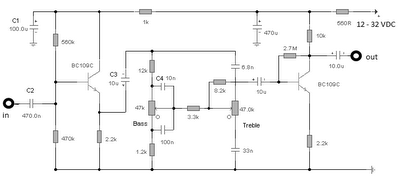
The first BC109C transistor functions as a buffer, delivering a high input impedance of approximately 250k and exhibiting a voltage gain marginally below unity. Given that the Baxendall tone control circuit operates passively, it attenuates all audio frequencies. The...
Here I propose a project of an AB class power amplifier, at its simplest, assembled with common components (not very expensive), based on traditional diagrams: a symmetrical differential input stage, a cascode stage driver, and a MOSFET output stage....
This preamplifier amplifies the signal from a microphone, an amplifier so that it can be further strengthened. The circuit supplies an output signal line. With two transistors, it is not difficult to build such a circuit. The amplifier produces...
Magnetic pickups in musical instruments exhibit a relatively high output impedance, which can lead to a decrease in treble response when connected through long cable runs or to equipment with low input impedance. This preamplifier addresses these challenges by...
Given the variety of equipment in modern home entertainment systems, the ability to adjust the gain of both audio and video signals has become essential. This particular circuit has proven to be very useful when used alongside the General...
Audio from a telephone line can be obtained using a transformer and capacitor to isolate the line from external equipment. A non-polarized capacitor is placed in series with the transformer line connection to prevent DC current from flowing in...