
Stereo preamplifier with bass circuit

The described preamplifier circuit is engineered to enhance audio signals from various sources, ensuring compatibility with equipment that may have lower sensitivity. The primary function of the preamplifier is to amplify the incoming audio signal by a factor of four, which is particularly beneficial when interfacing with power amplifiers that require a stronger input signal for optimal performance.
To further enhance the listening experience, the circuit incorporates a bass-boost feature, which is crucial for compensating for the inherent limitations of small loudspeaker cabinets that may not reproduce low-frequency sounds effectively. The bass-boost circuit allows for tailored adjustments to the low-frequency response, providing flexibility to the user. By utilizing a variable resistor, the user can fine-tune the bass boost from 0 dB, where no additional boost is applied, to a maximum of +16 dB at a frequency of 30 Hz. This adjustment capability ensures that the audio output can be optimized according to personal preferences or specific acoustic conditions.
For applications where a consistent bass boost is desired without the need for user adjustments, the variable resistor can be bypassed by incorporating a switch. This configuration allows for a fixed maximum boost level to be set, simplifying the operation for users who prefer a straightforward setup.
In terms of implementation, the circuit typically includes standard components such as resistors, capacitors, and operational amplifiers configured to achieve the desired gain and frequency response characteristics. Proper power supply decoupling and grounding techniques should be employed to minimize noise and ensure high fidelity in audio reproduction. Overall, this preamplifier circuit is a versatile solution for enhancing audio signals in various home audio applications.This preamplifier was designed to cope with CD players, tuners, tape recorders etc. , providing an ac voltage gain of 4, in order to drive less sensitive power amplifiers. As modern Hi-Fi home equipment is frequently fitted with small loudspeaker cabinets, the bass frequency range is rather sacrificed. This circuit features also a bass-boost, in or der to overcome this problem. You can use a variable resistor to set the bass-boost from 0 to a maximum of +16dB @ 30Hz. If a fixed, maximum boost value is needed, the variable resistor can be omitted and substituted by a switch. 🔗 External reference
Related Circuits
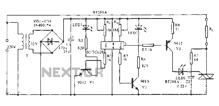
The built-in temperature sensor is utilized to control the triac TC620 for temperature regulation. The adjustment circuit, consisting of resistors Rp1 and Rn, allows for modifications to the lower temperature limit. When the ambient temperature exceeds this lower limit,...
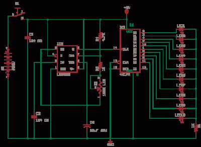
The 555 Astable generates a clock for this circuit, functioning as an oscillator that produces a square wave output at pin 3. This output is counted by the CD4017 decade counter, which creates a running lights effect. The CD4017...
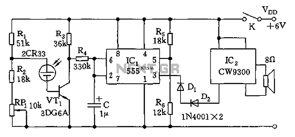
The circuit utilizes photoelectric sensors and a 555 timer to respond to music prompts. The illumination sensor components consist of photovoltaic cells (2CR33). When the light level drops below the optimal learning illumination of 100 lux, the 2CR33 exhibits...
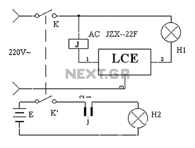
The application circuit operates the device as illustrated below, allowing for intermittent lighting in specific situations (e.g., during surgery). It utilizes an LCE module for blackout emergency lighting, which activates automatically after a power failure, ensuring uninterrupted illumination. In...
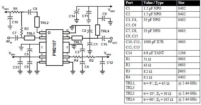
This RFIC amplifier operates in the 2400 MHz ISM band and features a two-stage design that is off-chip matched to ensure optimal performance across various applications. Powered by a 5-volt supply, the PM2107 can deliver 1 watt of saturated...
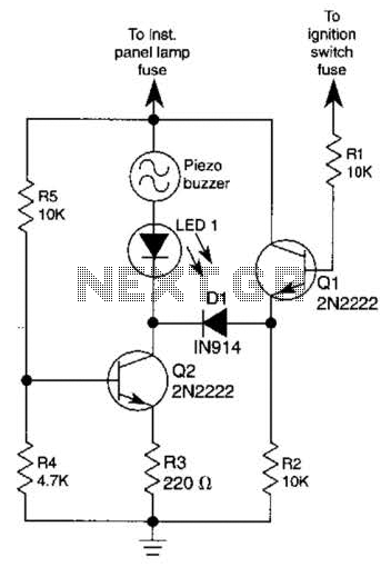
The base of Q1 is connected to the car's ignition circuit; the easiest point to make that connection is at the ignition switch fuse in the car's fuse panel. Also, one side of the piezoelectric buzzer is connected to...