
Series Inductor Filter

In electronic circuits, the implementation of an inductor filter is crucial for enhancing the performance of power supply systems, specifically in rectifier circuits. The inductor, or choke, acts as a passive component that stabilizes the output current by resisting rapid changes, thereby smoothing the output voltage. When the rectifier output generates a pulsed DC signal, the inductor stores energy during the peaks of this signal and releases it during the troughs, effectively reducing voltage ripple.
The inductor's impedance characteristics are essential to its filtering capability. At lower frequencies, the inductor presents minimal impedance, allowing DC components to pass through with little loss. Conversely, at higher frequencies, its impedance increases, which helps to attenuate AC ripple components. This property is particularly advantageous in applications where a stable DC output is required, such as in power supplies for sensitive electronic devices.
The relationship between the choke coil resistance (Rc) and the load resistance (RL) is critical for optimal performance. A small Rc ensures that the majority of the rectified voltage is available to the load, maximizing efficiency. The design of the inductor filter must consider the load conditions and the frequency of the ripple to ensure adequate filtering without excessive voltage drop.
In summary, the incorporation of a choke in series with a rectifier not only enhances the quality of the DC output but also provides a robust solution for managing ripple and improving overall circuit performance. The careful selection of component values and understanding of the circuit dynamics are vital for achieving desired results in practical applications.In this arrange ment a high value inductor or choke L is connected in series with the rectifier element and the load, as illustrated in figure. The filtering action of an inductor filter de pends upon its property of opposing any change in the current flowing through it.
When the output current of the rectifier increases above a certain value, e nergy is stored in it in the form of magnetic field and this energy is given up when the output current falls below the average value. Thus by placing a choke coil in series with the rectifier output and load, any sudden change in current that might have occurred in the circuit without an inductor is smoothed out by the presence of the inductor L.
The function of the inductor filter may be viewed in terms of impedances. The choke offers high impedance to the ac components but offers almost zero resistance to the desired dc components. Thus ripples are removed to a large extent. Nature of the output voltage without filter and with choke filter is shown in figure. where Vdc is dc voltage output from a full-wave rectifier. Usually choke coil resistance Rc, is much small than RL and, therefore, almost entire of the dc voltage is available across the load resistance RL.
Since the reactance of inductor increases with the increase in frequency, better filter ing of the higher harmonic components takes place, so effect of third and higher harmonic voltages can be neglected. As obvious from equation, if choke coil resistance Rc is negligible in comparisonto load resistance RL, then the entire dc component of rectifier output is available across2 RL and is equal to ” VL max.
The ac voltage partly drops across XL and partly over RL. 🔗 External reference
Related Circuits

Band-pass filter used for a single channel, fH 50Hz, fL 13kHz. A band-pass filter (BPF) is an electronic circuit that allows signals within a specified frequency range to pass through while attenuating signals outside that range. In this case, the...

This second-order low-pass filter utilizes a 741 operational amplifier and can be tuned from 2.5 kHz to 25 kHz. The circuit is beneficial in audio and tone control applications. R1 and R2 are ganged potentiometers. The described circuit features a...
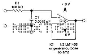
This simple filter utilizes an RC section as the filter element, incorporating a voltage follower to manage other frequencies. The -3 dB point is calculated as 1/(6.28 * RXCV), resulting in a response that drops 6 dB per octave...
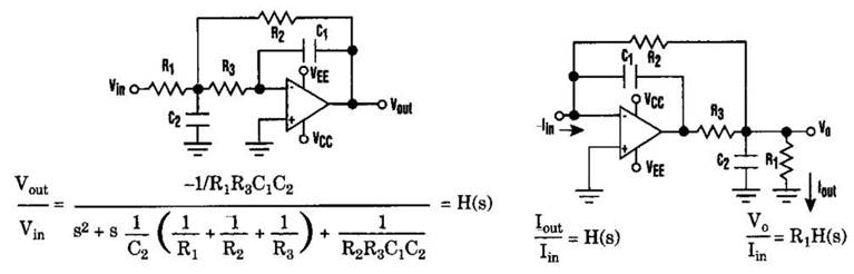
Current-Driven Sallen-Key Filter Circuit Diagram. The low-pass Sallen-Key filter is a staple for designers because it contains few components (A). The Sallen-Key filter is a widely used active filter topology that employs operational amplifiers (op-amps) to achieve desired filtering...
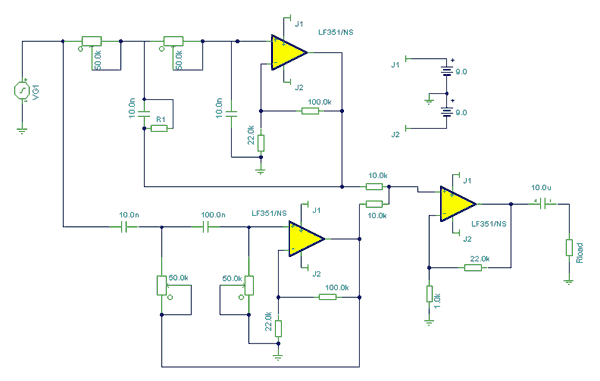
At first glance, this circuit appears to be quite complex; however, when analyzed, it can be segmented into high-pass and low-pass filter sections, which are subsequently connected to a summing amplifier with a gain of approximately 20 times. The...
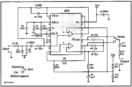
A simple circuit that can switch between a sharp cutoff frequency above 2.5 kHz and a narrow bandpass filter around 800 Hz. In the low-pass (LP) state, it is suitable for speech applications as the filter section of a...