
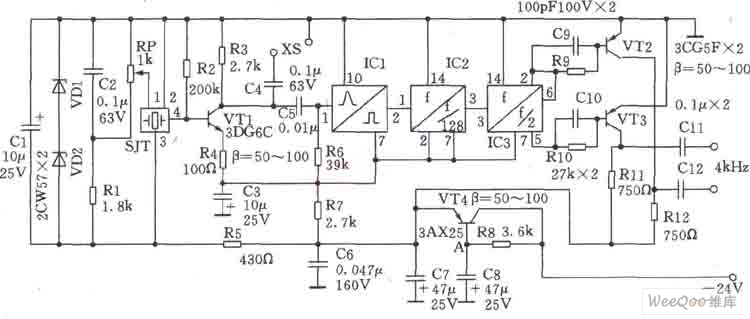
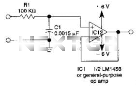
Low power monostable circuit diagram

The 555 Timer is a versatile integrated circuit commonly used in timer, delay, pulse generation, and oscillator applications. In a single-shot configuration, it operates as a monostable multivibrator, generating a precise output pulse in response to a triggering event. The CMOS4011B NAND gate can be utilized in conjunction with the 555 Timer to create complex logic functions or signal processing tasks, enhancing the circuit's functionality.
In this configuration, the standby power consumption of less than 50 µA ensures that the circuit remains energy-efficient, making it suitable for battery-operated devices. When the one-shot circuit is activated, the current consumption rises to 4.5 mA, which is necessary for driving the output load during the pulse duration. The pulse width, determined by the equation T = 1.1RC, allows for precise control over the timing characteristics of the output signal, where R is the resistance in ohms and C is the capacitance in farads.
This arrangement provides a reliable solution for applications requiring timed events or controlled signal generation, such as in timers, alarms, and various automation systems. The integration of the 555 Timer with the CMOS4011B NAND gate allows for additional logic processing, making it a valuable component in designing efficient electronic circuits.555 Timer enables low-loss single-shot circuit and CMOS4011B NAND gate circuit interface. Standby power consumption of less than 50 A. When the one-shot circuit is turned on, t he current consumption is 4.5mA, T pulse duration equal 1.1RC.
Related Circuits
Very often when enjoying music or watching TV at high audio level, we may not be able to hear a telephone ring and thus miss an important incoming phone call. To overcome this situation, the circuit presented here can...
This is a line follower designed to trace grid-type tracks. It features five line sensors for tracking the line. This arrangement of five sensors has proven effective, having been used multiple times with successful results. The device is named...
The voltage to be sampled is applied to the input of R2, a 100K linear taper potentiometer, while the other end of R2 is grounded. Consequently, the signal level that is sent to the buffering level shifter U1-A and...
This circuit is a 1024 kHz temperature-compensated crystal oscillator. The circuit theory is illustrated. Due to the low output signal level of the circuit, a buffer using the following transistor VT1 is implemented for amplification. The base bias resistor...
This simple filter utilizes an RC section as the filter element, incorporating a voltage follower to manage other frequencies. The -3 dB point is calculated as 1/(6.28 * RXCV), resulting in a response that drops 6 dB per octave...
A USBI2C can be utilized with each sensor, allowing for a configuration of four sensors at a cost of £120. The SRF02 operates on the I2C bus, which should not be extended beyond approximately 2 meters. The proposed solution...