
Low voltage flasher

The described circuit utilizes two silicon-controlled rectifiers (SCRs) in a configuration that allows for controlled triggering and commutation. When a voltage is applied, SCR1 becomes conductive, allowing current to flow through it. This action raises the voltage at the anode of SCR2, which is connected in a manner that it remains off until the appropriate voltage is reached. Once the voltage at the anode of SCR2 exceeds its triggering threshold, SCR2 conducts, effectively providing a path for current that can turn off SCR1.
The behavior of SCR1 is influenced by the voltage at its gate. During the operation, when SCR1 is triggered, the gate voltage experiences a negative swing due to the feedback from SCR2. This negative swing is critical for the commutation process, as it helps to turn off SCR1. However, it is essential to ensure that this negative voltage does not exceed -6 volts, as exceeding this limit could lead to damage or malfunction of SCR1.
For applications requiring higher voltage levels, careful consideration must be given to the voltage ratings of both SCRs and the components surrounding them. The design must ensure that the SCRs can handle the maximum expected voltage and current levels without exceeding their specified limits. Additionally, appropriate protective measures, such as snubber circuits or voltage clamps, may be implemented to safeguard against transient voltages that could occur during operation.
This circuit configuration is widely applicable in power control systems, motor drives, and other applications where controlled switching of high voltages is necessary. Proper thermal management and heat dissipation strategies should also be considered to enhance the reliability and longevity of the SCRs in the circuit.Applying voltage to the circuit triggers SCR1. With SCRl on, the voltage on the anode of SCR2 rises until SCR2 triggers to commu-tate SCRl. The voltage on the gate of SCRl will swing negative at this time, and only after a positive potential of 0 volt is once again attained, will SCRl retrigger The circuit could be used for higher voltage levels, but the peak negative voltage on the gate of SCRl must be limited to less than 6 volts.
Related Circuits

This is a simple and low-cost NiCd and NiMH battery charger. The schematic diagram indicates that the charging current (I) should be set to 1/10 of the battery's rated capacity. For instance, if the battery has a rated capacity...
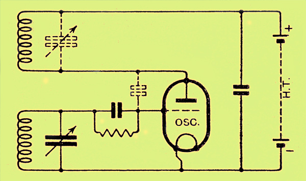
The congestion of the ether is increasing, prompting ongoing efforts to extend communication channels to higher frequencies. Wavelengths as short as 12 meters are now common, but operating below this presents significant challenges. At approximately one meter, the oscillation...
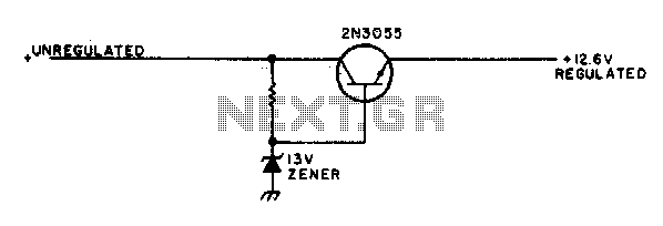
This simple mobile voltage regulator circuit may save your two-meter or CB transceiver if the voltage regulator fails. The 2N3055 should be heat-sinked if the current drawn by the rig exceeds 2 A during transmission. This circuit will do...
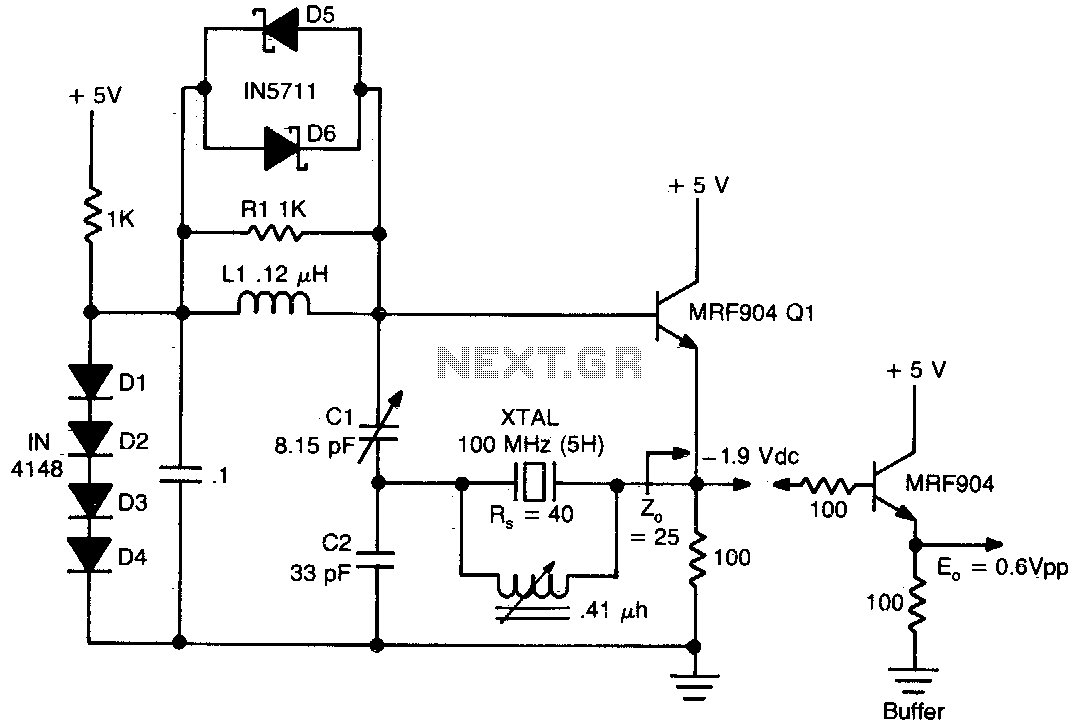
This circuit exhibits good performance without an amplifier, having a gain of only one, with built-in parasitics due to the emitter follower negative feedback. Additionally, it serves to stabilize its gain. The circuit under discussion utilizes an emitter follower configuration,...
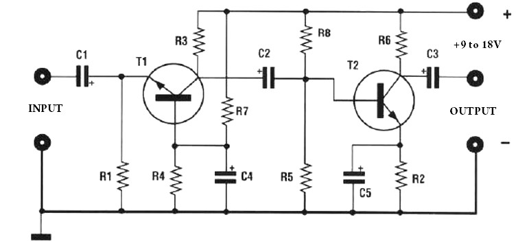
The amplification of this preamplifier is very high. To reduce the amplification, a trimmer resistor R3 in series with a value of 100 ohms should be used. The system can be powered by a voltage ranging from 9 to...
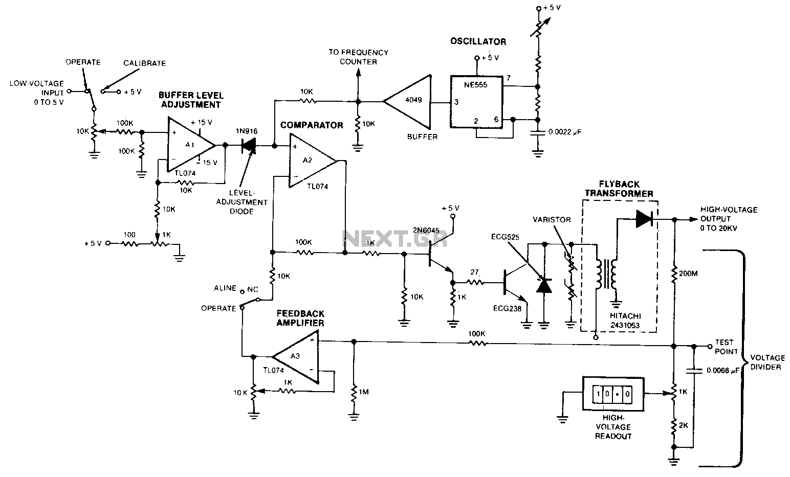
The output voltage varies approximately linearly up to 20 kV as the input voltage is adjusted from 0 to 5 V. A 5-0 potentiometer is used to tune the oscillator, optimizing the output voltage at the frequency of maximum...