Low-Voltage Remote Mains Switch
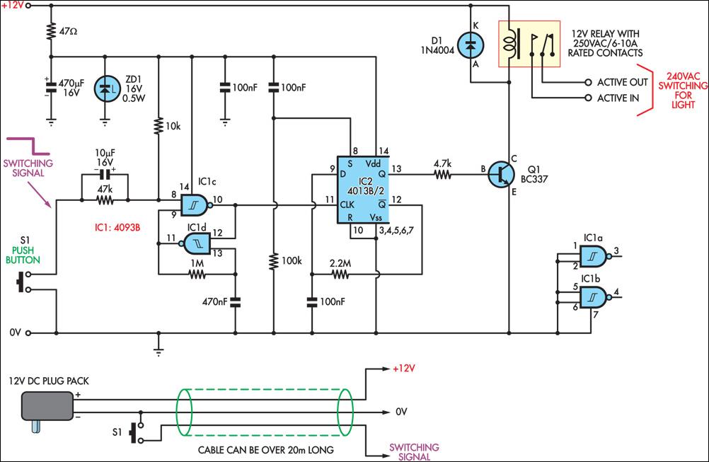
This circuit enables the remote control of a 240V mains appliance, such as a light bulb, through low-voltage cabling and a pushbutton switch. The mains appliance is activated using a suitably-rated relay. All electronic components are housed in an ABS enclosure positioned near the appliance, while the pushbutton switch and power supply are located at a distance. The system can be wired using 3-core alarm cable or similar types, allowing for cable lengths of 20 meters or more. When the switch (S1) is pressed, the input (pin 8) of IC1c is briefly pulled low through a 10μF capacitor, which starts in a discharged state. This action causes the output (pin 10) to go high, which is then inverted and fed back to the second input (pin 9) via another gate in the quad NAND package (IC1d). The combination of a 1MΩ resistor and a 470nF capacitor in IC1d mitigates the effects of contact bounce, ensuring that the output from IC1c remains high for a set duration. The output from IC1c drives the clock input of a 4013 D-type flip-flop (IC2), configured for toggle operation by connecting the Q-bar output back to the D input. Additionally, a 2.2MΩ resistor and a 100nF capacitor enhance the circuit's noise immunity. Each press of the switch toggles the flip-flop output (pin 13), activating or deactivating the transistor (Q1) and the relay. It is crucial that all mains wiring is properly installed and fully insulated to prevent contact with the low-voltage side of the circuit.
This circuit design utilizes a relay to control high voltage appliances safely while maintaining a low-voltage control interface. The choice of using an ABS enclosure ensures durability and protection of the electronic components from environmental factors. The pushbutton switch and power supply can be located at a significant distance from the appliance, making this design suitable for various applications where remote operation is required.
The use of a quad NAND gate (IC1) in the circuit serves a dual purpose: it not only processes the switch input but also provides debouncing to eliminate false triggering caused by mechanical bounce in the switch contacts. The timing characteristics of the circuit can be adjusted by modifying the values of the resistor and capacitor in conjunction with IC1d, allowing for flexibility in response time based on user requirements.
The 4013 D-type flip-flop (IC2) is a key component in this design, providing a simple yet effective means of toggling the relay state with each press of the switch. The feedback mechanism through the Q-bar connection ensures that the output state changes reliably, making the circuit responsive and efficient. The additional components, such as the 2.2MΩ resistor and 100nF capacitor, further increase the robustness of the design by filtering out noise that could affect the operation of the flip-flop.
In summary, this circuit provides a practical solution for remote control of mains appliances, emphasizing safety, reliability, and adaptability to different installation scenarios. Proper attention to insulation and installation practices is essential to ensure the safe operation of the circuit and to prevent any potential hazards associated with high voltage exposure.This circuit allows a 240V mains appliance to be controlled remotely via low-voltage cabling and a pushbutton switch. The mains appliance (in this case, a light bulb) is switched with a suitably-rated relay. All of the electronics is housed in an ABS box located in proximity to the appliance. The pushbutton switch and plugpack are located remotely and can be wired up with 3-core alarm cable or similar. Cable lengths of 20m or more are feasible with this arrangement. When the switch (S1) is pressed, the input (pin 8) of IC1c is briefly pulled low via the 10mF capacitor, which is initially discharged. The output (pin 10) immediately goes high and this is inverted and fed back to the second input (pin 9) via another gate in the quad NAND package (IC1d).
In conjunction with the 1MW resistor and 470nF capacitor, IC1d eliminates the effects of contact "bounce" by ensuring that IC1c`s output remains high for a predetermined period. The output from IC1c drives the clock input of a 4013 D-type flip-flop (IC2). The flipflop is wired for a "toggle" function by virtue of the Q-bar connection back to the D input. A 2. 2MW resistor and 100nF capacitor improve circuit noise immunity. Each time the switch is pressed, the flipflop output (pin 13) toggles, switching the transistor (Q1) and relay on or off.
Note that all mains wiring must be properly installed and completely insulated so that there is no possibility of it contacting the low-voltage side of the circuit. 🔗 External reference
