
Low Voltage to 30 kV Out

The circuit employs a flyback transformer sourced from older televisions or monitors. The input voltage is connected to a transistor (Q1), typically a 2N3055, configured in a switching arrangement to drive the transformer. The circuit includes a high voltage (HV) diode for rectification, essential for converting the AC output from the transformer into a usable high voltage DC. The secondary winding of the flyback transformer is responsible for generating the high voltage output.
In terms of components, resistors R1 and R2 are used to limit the current flowing through the transistors and to stabilize the operation of the circuit. The design may require a heat sink to manage the thermal load on the transistors, especially when utilizing larger flyback transformers or higher input voltages. For improved performance and reliability, it is advisable to use transistors with higher power ratings, particularly in applications involving sustained operation.
For modifications, an inductor (L1) can be added to the circuit to reduce stress on the transistors and the power supply by limiting current during the switching transitions. This modification has been utilized successfully in similar inverter designs.
When selecting a flyback transformer, it is crucial to ensure that the high voltage secondary winding is intact and that the primary winding is in good condition. If the primary winding has failed, it may be removed without damaging the secondary winding. It is important to identify the return path for the high voltage winding, which may be indicated by a different color wire or a separate exit point from the transformer. Testing for continuity with an ohmmeter may not be effective if the transformer has an integrated high voltage rectifier, as the forward voltage drop will exceed the multimeter's battery voltage. A winding showing infinite resistance to all other terminals is likely the high voltage return.
Overall, this circuit allows for the generation of high voltage from a low voltage source, suitable for various applications, including high voltage experiments and gas discharge excitation. Proper precautions and component selections are necessary for safe and effective operation.The basic circuit described in this document is capable of generating up to 30 kilovolts or more from a low voltage DC source using the flyback (LOPT) transformer salvaged from a B/W or color TV or computer monitor. Typical output with a 12 VDC 2 A power supply or battery will be 12, 000 V. Maximum output current at full voltage is typically around 1 to 2 mA. Higher currents are available but the output voltage will drop. At 2 kV, more than 10 mA may be possible depending on your particular flyback transformer input voltage and current. Before thinking about experimenting with anything using or producing high voltages, see the document: Safety Guidelines for High Voltage and/or Line Powered Equipment.
While the circuit described below isn`t likely to be lethal using the suggested input voltage and components, who knows how you might `enhance` it! :-) +Vcc Q1 +-+ o | ):: | B |/ C ):: | +-| 2N3055 ):: | | | E 5 T ):: +-|>|-o +HV | | | )::( HV Diode, usually | | -_- )::( built in.
| | )::( +-|-+ ::( | | Q2 _-_ )::( | | | )::( Secondary (HV) winding, | | B |/ E 5 T )::( intact. | | -| 2N3055 )::( | | | | C )::( | | | | )::( | | | +-+ ::( | | | ::( | | -+ :: +-o -HV | | 2 T ):: | | +-+ :: | | | 2 T ):: T1 - Flyback transformer from B/W or | +-+ color TV or computer monitor. | | | R1 | R2 +-///-+-///-+ 110 27 _|_ 5 W 5 W - TO3Pn TO220 _ _ / | o | | O | View from front (label side).
|-| |-| |Label| | | B = Base, E = Emitter, C = Collector. |_| | Label | | | | |_| If there is an exposed metal tab, that is | | | | | | the Collector as well. B C E | | | B C E A slightly modified version of this basic circuit which I use as an RF source to excite a glow discharge in helium-neon laser and other gas discharge tubes is shown in: Flyback Based RF Source. This one uses a flyback transformer without a high voltage rectifier (or with the rectifier removed).
The inductor, L1, is an addition that should reduce the stress on the transistors and power supply by limiting current at the time each of the transistors go into saturation just before the base drive switches to the opposite side. I have not specifically tested this circuit with the inductor but have used it with similar inverters.
These designs are similar to circuits found in: "Build your own working Fiberoptic, Infrared, and Laser Space-Age Projects", Robert E. Iannini, TAB books, 1987, ISBN 0-8306-2724-3 and many other places. For larger (e. g. , color TV or monitor) flybacks, or use with more than 12 VDC in, transistors with higher power ratings may be needed for sustained operation in addition to a good heat sink.
An alternative is to parallel more than one power transistor along with small (e. g. , . 05 ohm, 2 W) current balancing resistors in series with their emitters. Read the following in its entirety! This assumes the basic circuit using a small flyback and input voltage of 12 VDC or less. Some modifications may be needed when using larger flybacks and higher input voltages. Obtain flyback transformer with known good HV secondary winding. primary may be left intact if it is known to be in good condition - non shorted. A flyback removed due to failure may be used if it was the primary that failed and the primary turns can be removed without damaging the HV secondary or losing the secondary return connection! Flybacks fail in both ways (primary and secondary). Locate the return for the high voltage winding. This may be a different color wire than the low voltage winding or may exit from the potted part of the flyback in a different place.
It is not possible to use an ohmmeter to locate the return for the high voltage winding if your flyback has a built-in HV rectifier or multiplier as the forward voltage drop of the rectifier diodes is much greater than the battery voltage used in your multimeter. However, a winding connection that has infinite resistance to every other terminal is likely to be the HV return
🔗 External reference
Related Circuits
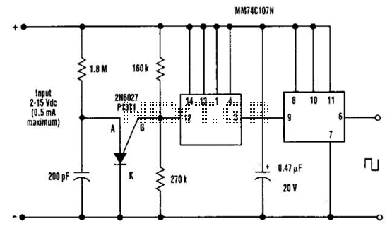
A direct current (DC) voltage source within the range of 2 to 15 volts can be converted into a unipolar square wave. This square wave has a peak amplitude that is nearly equal to the DC source voltage, with...
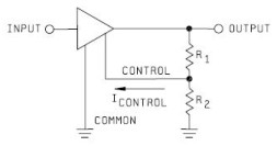
Neither term describes a regulator, only its placement within a circuit or system. Any voltage regulator could meet the requirements, depending on its placement. A listing of Analog Voltage Regulator IC manufacturers. The types of products or devices they...
The technical parameters of high-speed optocouplers include a rise time (t1) of less than or equal to 300 ns, a circuit transfer ratio (CTR) of 50%, an isolation voltage (VSO) of at least 15,000 V, and an output transistor...
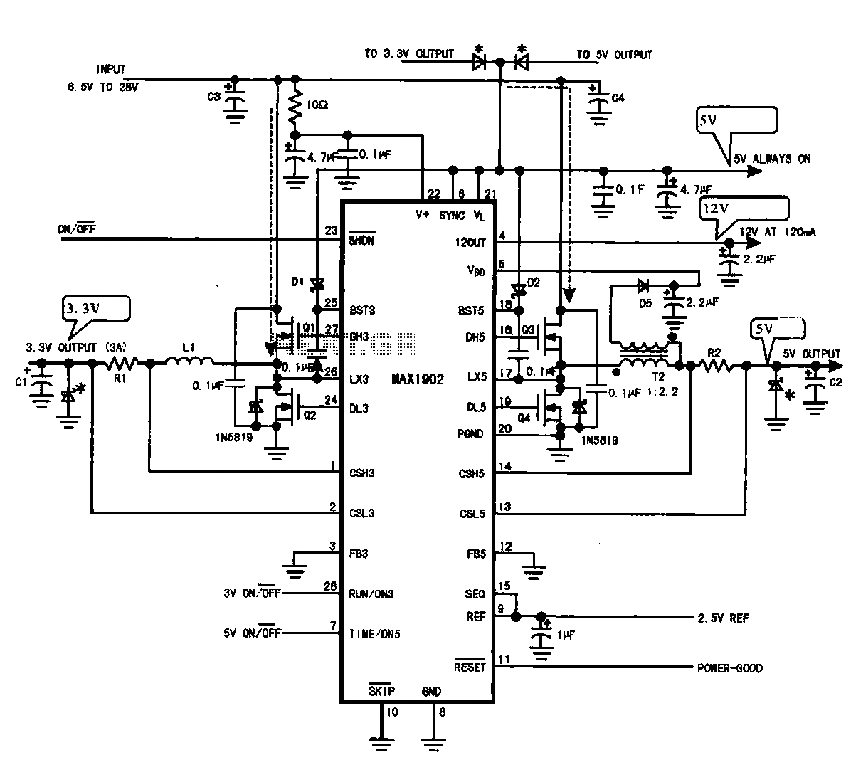
Multi-output power supply circuit (MAX1902). This circuit illustrates the power supply configuration for a notebook computer motherboard, utilizing the MAX1902 chip for power control. It is designed to convert the battery's DC voltage into multiple DC voltage outputs. The multi-output...

This series-feedback configuration of components provides a high input impedance and stable, wide-band gain video amplifier suitable for general-purpose applications. Below is the schematic representation of the circuit. The described video amplifier circuit employs a series-feedback topology, which is instrumental...
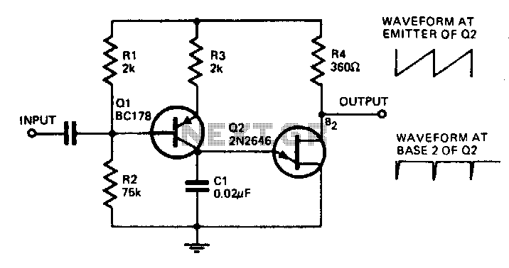
With the component values shown, the oscillator has a frequency of 8 kHz. When an input signal is applied to the base of Q1, the current flowing through Q1 is varied, thus affecting the time required to charge C1....