
magnetic stripe reader circuit

In a magnetic stripe reader circuit, the proper configuration of components is critical for accurate operation. The circuit typically includes a magnetic sensor, a signal processing unit, and an output interface. The transistor plays a vital role in amplifying the signal received from the magnetic stripe reader.
In this particular wiring diagram, the transistor's collector is connected to the tip pin of the jack, which serves as the output connection to the next stage of the circuit or to an external device. This connection is essential for transferring the amplified signal generated by the transistor.
The base pin of the transistor is connected to the junction of a 120,000-ohm resistor and a 470-nanofarad capacitor. This configuration forms a biasing network that controls the transistor's operation. The resistor limits the current flowing into the base, while the capacitor couples the AC signal from the magnetic stripe reader to the base of the transistor. This allows the transistor to switch on and off in response to the magnetic stripe's information, effectively converting the analog signal into a digital format that can be processed further.
It is crucial to ensure that the transistor is correctly wired in the circuit to avoid malfunction. The absence of a connection to the transistor may lead to a failure in signal amplification, rendering the magnetic stripe reader ineffective. Proper attention to the component values and connections will facilitate a reliable and efficient operation of the magnetic stripe reader circuit.magnetic stripe reader, electric circuit theory, logic operation: Your wiring diagram does not connect the transistor in the circuit. The collector pin of the transistor connects to the tip pin of the Jack. The base pin of the transistor connect to the junction of the 120,000 ohm resistor and the 470 nanofarad capacitor..
🔗 External reference
Related Circuits
The primary components of this doorbell circuit include two NE555 timer integrated circuits (ICs). When the switch S1 is pressed momentarily, the loudspeaker emits a bell tone for the duration determined by the time period of the monostable multivibrator...
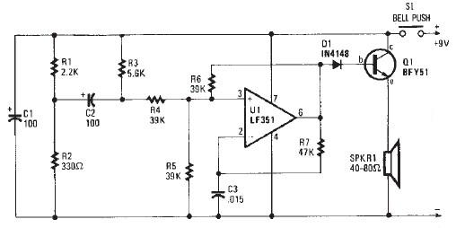
This electronic door buzzer circuit schematic has a straightforward function and is simple to construct. The circuit employs an LF351 operational amplifier along with a few common electronic components. When the S1 push-button is pressed, a positive voltage is...

The circuit depicted in Figure 3-22 includes KMi and SBi as forward contacts and forward buttons, KMz and SB2 as reverse contactors and reverse buttons, with SB3 designated as the stop button. The circuit in question is likely part of...
The image depicts a proximity switch circuit that includes the HMC1001 Hall effect sensor, an operational amplifier (AMP04), and a light-emitting diode (LED). In this configuration, the operational amplifier functions as a comparator. When a magnet with a length...

This function generator, based on an LT1016 high-speed comparator, will generate from a single +5-V supply. The slow rate of the op-amps used determines the maximum usable frequency of this circuit. The function generator utilizes the LT1016 high-speed comparator to...

A simple ultrasonic parking sonar electronic project can be designed using this schematic circuit. This ultrasonic parking sonar project features an adjustable detection range from 5 cm to 1.5 meters and a detection angle of 5 degrees. The circuit...