
make mini logic analyzer

The mini logic analyzer circuit is designed for versatility and ease of use in digital signal monitoring. The core component, the AVR microcontroller, plays a critical role in processing the input signals and managing the data acquisition process. The use of pull-down resistors ensures that the inputs remain stable and do not trigger false readings due to noise or interference. The LCD display, specifically the Nokia 3310/5110 model, is selected for its low power consumption and adequate resolution for displaying the captured data. The implementation of diodes to adjust the voltage for the LCD backlight is a thoughtful design choice, ensuring that the display functions correctly without risking damage.
The data acquisition process is efficient, with the microcontroller capable of capturing and storing multiple samples in quick succession. The design allows for user interaction through the buttons, enabling real-time adjustments to the display of the captured data. This flexibility is particularly useful for analyzing signals that vary in frequency, providing users with the ability to zoom in or out on the data for better clarity. Overall, the mini logic analyzer circuit exemplifies a well-structured approach to digital signal monitoring, making it a valuable tool for engineers and hobbyists alike.This mini Logic analyzer is a tool for you to watch on LCD the logic transitions 0 or 1 of a digital data signal. A digital data signal can be found on the output pin of TSOP-1730 Infrared Receiver, on the Transmit and receive pins of MAX-232 chip (RS-232), on Clock and Data pins of I2C data bus and many more electronic components.
This circuit su pports capturing for up to 100 kHz digital signals. The operating voltage of the circuit is 4. 8V DC from 4x1. 2V rechargeable batteries. Switch on the S1 to power on the electronic circuit. After the initial screens on LCD you will see a message that the AVR waits for a signal change on input pins. The AVR has 4 external pull-down resistors 33kG™ (R2-R5) avoiding any unnecessary trigger on any input pin because of an external electromagnetic field or by touching accidentally your hand on any input pin.
The Nokia 3310/5110 LCD works from 3. 3 - 5V power supply. The problem is that the LCD`s backlight works with Maximum 3. 3V DC. So I put diodes D1-D3 to decrease the voltage from 4. 8V to 4. 8-(0. 7*3)=2. 7V that is the required power supply of Nokia`s LCD. When you power ON the circuit, the LED1 is turned OFF. After the first trigger on any of 4 input pins, this LED is turned ON and the AVR starts capturing the data in to its internal RAM buffer (290 samples). Do not use regular alcaline 1. 5V batteries instead of rechargeable. The total voltage is 4 x 1. 5 = 6V. This voltage will probably burn the LCD and the AVR microcontroller. As you can see on Picture 5 the data buffer is constituted by 870 bytes (v1. 00) 2 for the counter and one for the input pins information. In version 1. 01 the data buffer was decreased to 256*3=768 bytes for increasing the capturing speed because the buffer size variable is 8 bit instead of 16 bit that I used before.
The next byte calculations must be done according to the firmware version you use. How it works It is simple. After the power ON the AVR waits for a trigger pulse on any of 4 input pins. If a trigger pulse is detected the AVR starts counting the time is needed for the next trigger on any of the 4 input pins. The sample length is stored in a 16-bit variable named "counter". When this variable overflows, the status of the 4 input pins and the counter value are stored in the buffer and its address is increased by 3 (2 bytes for counter and 1 byte for input pins data).
This process is been made until the AVR fills all the buffer bytes (870/3 = 290 samples or triggers). When the AVR fills the buffer, all the data are appeared on LCD as a graph. You can move the graph to the left ( button S3) or to the right (button S4) to watch the entire data sequence.
If the data sequence is in a low speed you can shrink the graph (zoom out) with a 2, 4, 8, 16, 32, 64, 128, 256, 512, 1024, 2048, 4096 or 8192 ratio by pressing the S2 button. 🔗 External reference
Related Circuits
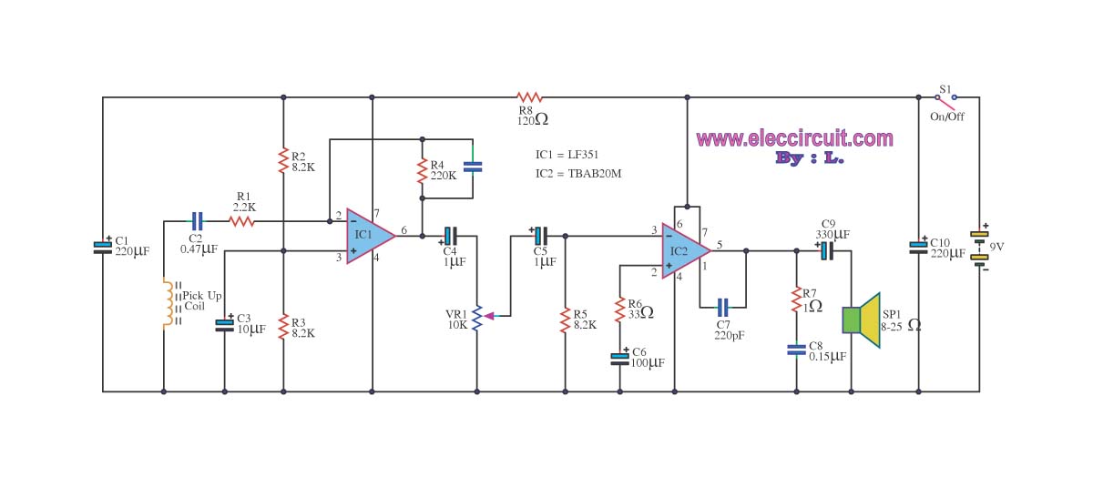
The circuit is designed to amplify telephone signals using a 2W+2W amplifier with an 8-ohm loudspeaker. It provides adequate sound output while maintaining good audio quality. The primary component of this telephone amplifier circuit is the IC LF351, which...
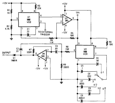
When this circuit is connected to a filter and an oscilloscope, the oscilloscope displays the filter's frequency response. A frequency that sweeps from low to high is applied to a filter. The oscilloscope is triggered by the start of...
The circuit shown in Figure 1 uses only two ICs, and has a bandwidth that is adjustable from more than one octave down to a tenth of an octave. As shown, the frequency range is 20 Hz. to 20...
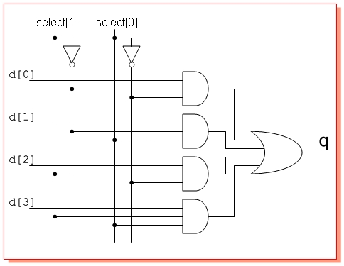
Design a circuit with four single-bit inputs X, Y, T, and Z, and a single-bit output E. A two-bit control code word S0S1 determines which of the four inputs is sent to the output (the selection code is not...
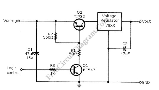
Logic power control of an analog regulator can be useful in applications where a digital circuit or controller needs to manage a power source, such as in EEPROM programmers or other power control systems. This circuit provides ON-OFF control...
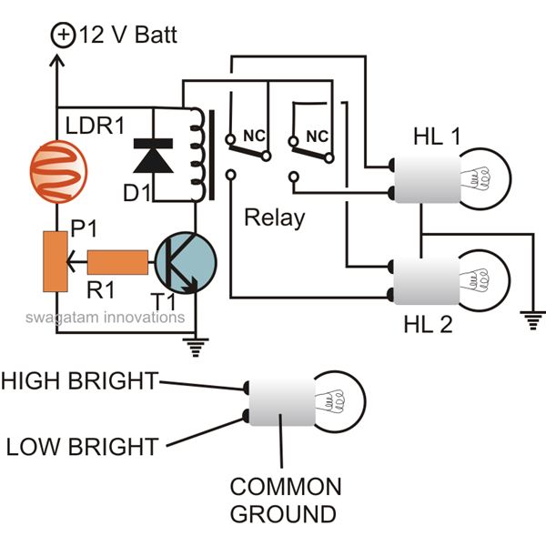
The circuit described here can be built and used in a vehicle for an automatic dipping and dimming operation of the headlamps in response to intense lights coming from opposite vehicle headlamps. This situation is often encountered while driving...