
make this solar powered fence charger

The solar electric fence charger circuit is designed to efficiently convert solar energy into a high-voltage output suitable for energizing electric fences. The primary components of this system include a solar panel, a charge controller, a 555 timer IC configured as an oscillator, an ignition coil, and a transformer.
The solar panel captures sunlight and converts it into direct current (DC) electricity. This DC output is regulated by a charge controller, which ensures that the battery is charged optimally while preventing overcharging. The charge controller also provides a stable voltage to the 555 timer oscillator.
The 555 timer is configured in astable mode, generating a square wave output that switches at a predetermined frequency. This output is fed into the primary winding of the ignition coil. The ignition coil is designed to increase the voltage significantly; when the 555 timer activates the coil, it induces a high voltage in the secondary winding due to the principle of electromagnetic induction. This high voltage is then routed to the electric fence, creating a deterrent for intruders.
Additionally, the transformer plays a critical role in stepping up the voltage to the desired level. The output voltage from the transformer is typically around 220V AC, which is necessary for the operation of the ignition circuit. The system is designed to operate continuously, ensuring that the electric fence remains energized day and night, providing reliable security for the enclosed area.
In summary, the solar electric fence charger is a self-sufficient system that leverages renewable energy to provide a high-voltage output for electric fencing applications, making it an ideal solution for remote areas where traditional power sources are unavailable. The integration of solar technology with high-voltage generation components creates an efficient and effective means of protecting property from unwanted intrusions.A Fence charger or energizer is an equipment which is used for charging(electrifying) a fence or a boundary in order to protect the inside premise from human or animal interventions. Since these boundaries are mostly of large fields and parks, are normally away from the main cities, and powering them through some renewable option becomes more
suitable than from utility grids which may become difficult to acquire in such remote areas. The circuit of a solar electric fence charger explained here does not depend on traditional power source for operating, rather gets it 24/7 from a self sustained solar power conversion set up. The sudden dumping of the above high voltage inside the ignition coils primary, steps up the surge into several thousands of volts into the secondary winding of the ignition coil.
The triggering circuit consists of a IC 555 oscillator which switches the voltage obtained from the solar panel controller into the transformers input, so that the output from the transformer generates the required 220V AC for powering the ignition circuit. 🔗 External reference
Related Circuits
This is a solar tracking circuit designed to harness power from sunlight. The circuit operates optimally by maximizing sunlight exposure to generate electricity. The solar tracking circuit utilizes a combination of photovoltaic (PV) cells, sensors, and a microcontroller to adjust...
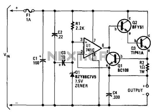
A regulator enables the powering of a 7.5-V cassette recorder or other devices from a 12-V DC automotive system. The circuit can provide approximately 600 mA of current. Q3 requires a heatsink due to its potential to dissipate up...
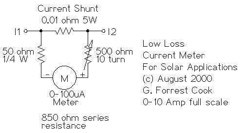
This circuit is used to measure the current from a solar panel. It has very low power loss for currents in the 0-10A range. It also works as a general purpose DC current meter. The circuit can be used...
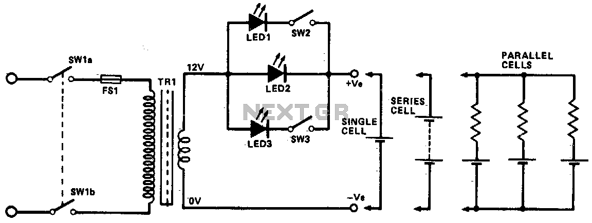
This circuit utilizes constant current LEDs to regulate the charging current. It employs LEDs that maintain a consistent current of approximately 15 mA across an applied voltage range of 2 to 18 V. The LEDs can be connected in...
The phone company provides 3 levels of power. With no devices 'off hook' the line rests at 48 volts DC. If you draw any more than a fraction of a milliamp or so, you get the phone company's attention...
A solar panel is a device that collects solar energy and converts it into electricity. It consists of a backing material on which solar cells are affixed. These cells are interconnected, ultimately linking to an electric wire that can...